Undulated-wall honeycomb structure and manufacturing method thereof

a honeycomb and honeycomb technology, applied in combination devices, air quality improvement, dispersed particle filtration, etc., can solve the problems of increasing pressure loss, not allowing the passage of exhaust gas through the cell passage, etc., to increase the ratio of area, increase thermal capacity, and improve the ability to remove fine particles

Inactive Publication Date: 2010-02-02
NGK INSULATORS LTD
View PDF33 Cites 27 Cited by
  • Summary
  • Abstract
  • Description
  • Claims
  • Application Information

AI Technical Summary

Benefits of technology

[0022]With the undulated-wall honeycomb structure according to the present invention, regarding each of the cell passages, at least one of the plurality of walls making up the cell passage is preferably formed with an undulated shape, i.e., such that there are no cell passages that do not come into contact with a wall formed with an undulated shape. Also, the degree of undulated deformation whereby the walls are formed with an undulated shape is preferably greater at the outer portion that at the center portion, thereby essentially not allowing passage of exhaust gas through the cell passages at the outer portion. Thus, the advantages of preventing heat discharge from the periphery portion, intensifying the mechanical strength of the periphery portion, and preventing excessive precious metal components from being carried by the periphery portion, as disclosed in JP-A-49-63821 and JP-A-56-129042, can be obtained.
[0040]Other examples of applications of the undulated-wall honeycomb structure according to the present invention include as a catalyst carrier for modifiers for fuel cell systems or for the fuel cells themselves, as part of a fuel tank evaporation system for suppressing external leakage of volatile components of fuel, or even as a sandwich panel.

Problems solved by technology

Also, the degree of undulated deformation whereby the walls are formed with an undulated shape is preferably greater at the outer portion that at the center portion, thereby essentially not allowing passage of exhaust gas through the cell passages at the outer portion.
However, excessive deformation invites increased pressure loss, so the amount of amplitude of deformation is optimized for each cell structure by balancing the degree of improvement in cleaning capabilities and increase of pressure loss, while comparing with engine performance.

Method used


Image

  • Undulated-wall honeycomb structure and manufacturing method thereof
  • Undulated-wall honeycomb structure and manufacturing method thereof
  • Undulated-wall honeycomb structure and manufacturing method thereof

Examples


embodiments

[0138]Next, the properties of the undulated-wall honeycomb structure according to the present invention will be described with comparison to a conventional honeycomb structure.

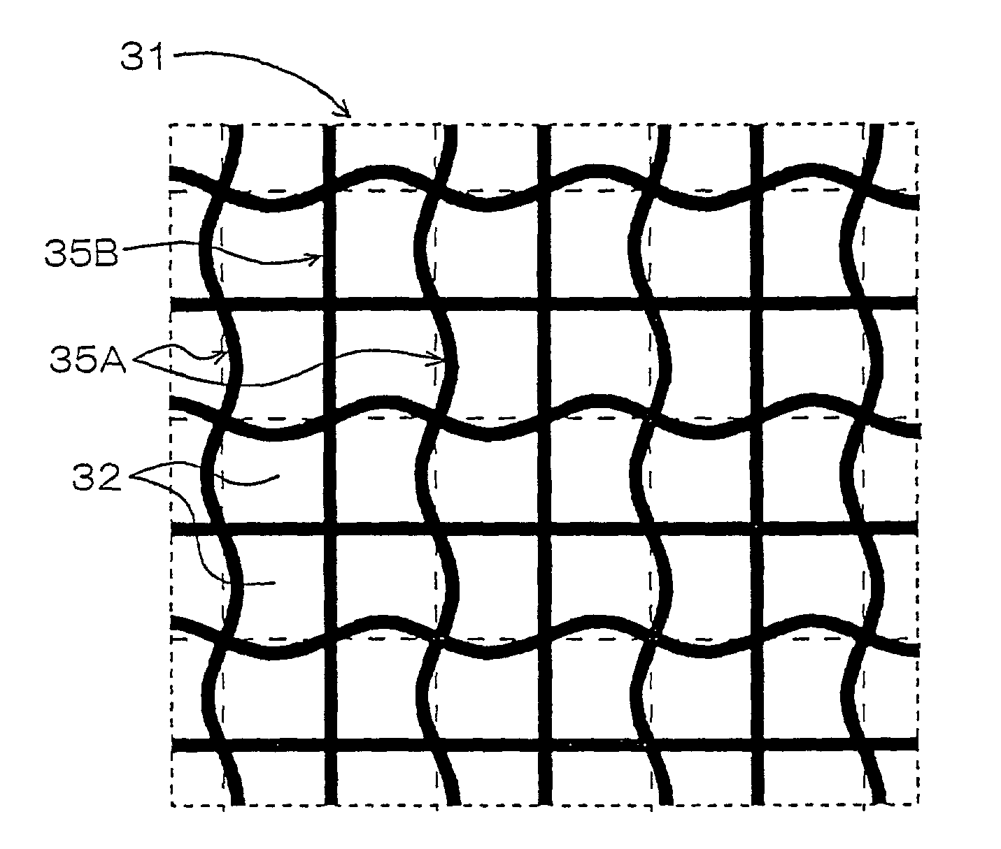
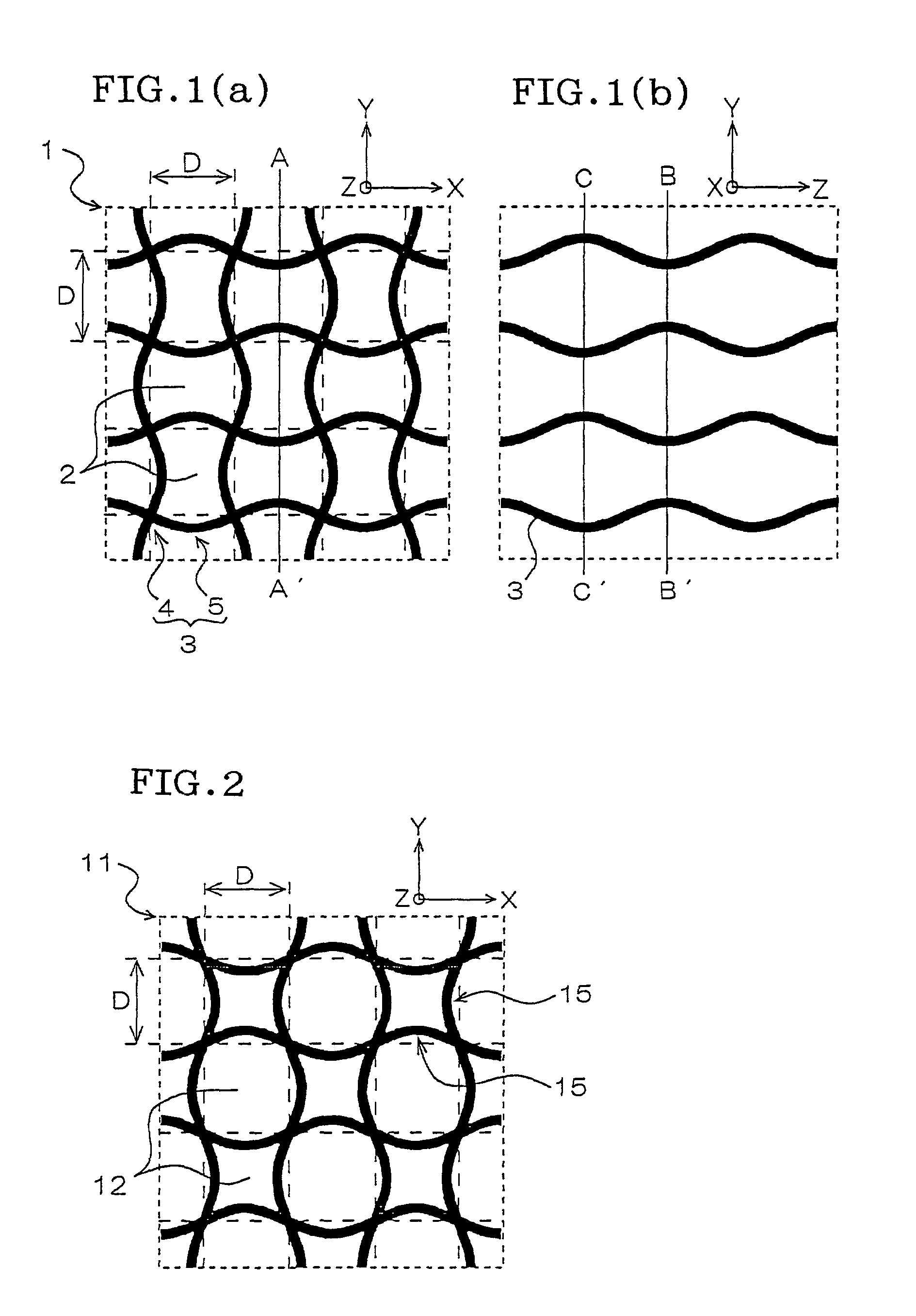
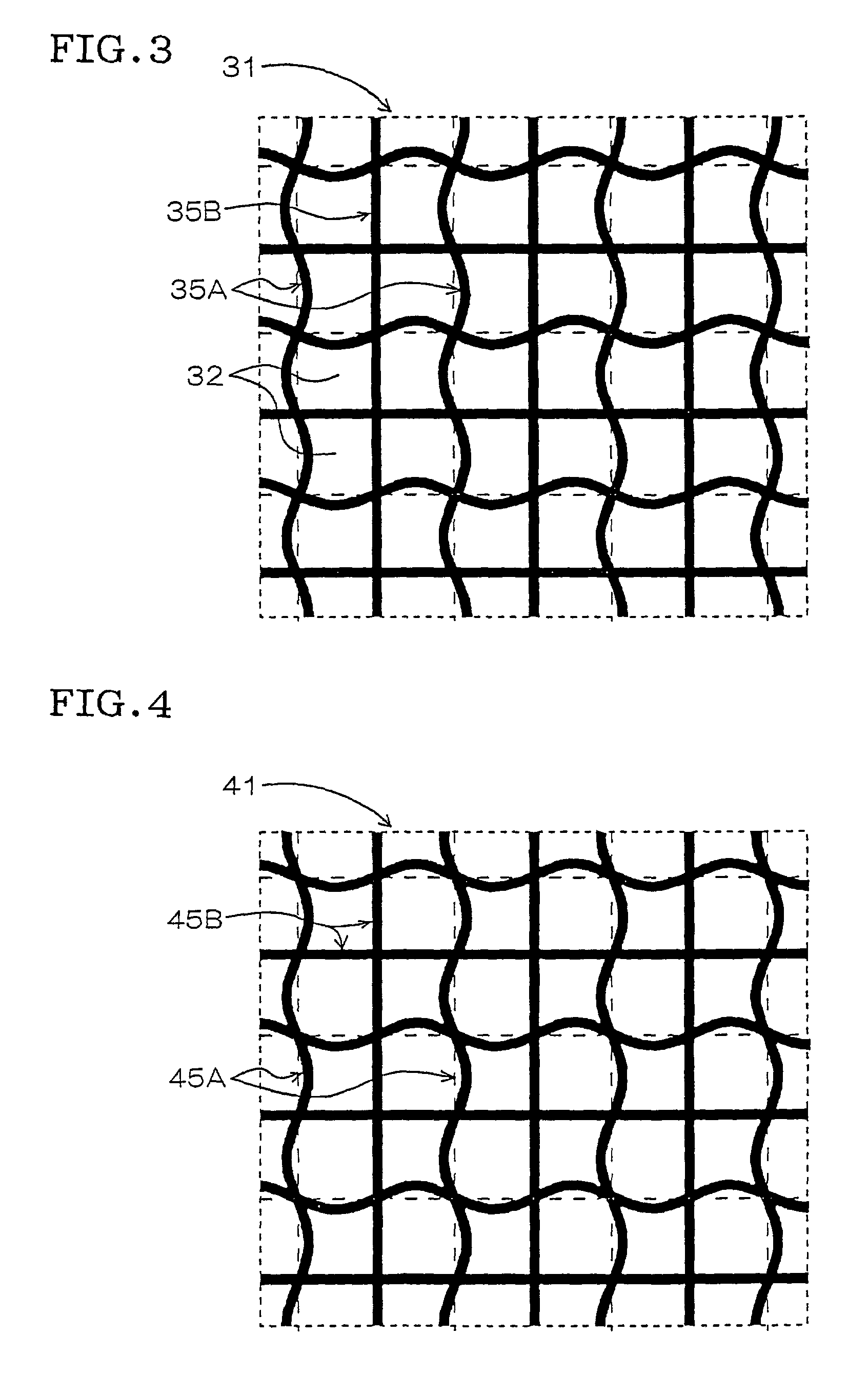
[0139]For the materials, water and binder is added to cordierite of which the main ingredients are talc, kaolin, and alumina, the mixture is kneaded, an undulated-wall honeycomb structure 1 (first embodiment) with all walls formed with undulated shapes as shown in FIGS. 1 (a) and (b) and an undulated-wall honeycomb structure 31 (second embodiment) wherein undulated walls and flat walls are mixed as shown in FIG. 3 are formed using the recessed back plate wherein the thickness changes and the back plate wherein the diameters of the through holes differ, and the articles were cut to predetermined lengths and baked following drying, thus obtaining the present invention.

[0140]Also, for the sake of comparison, a normal honeycomb structure (first comparative example) wherein there are no undulated deformations on th...


PUM

PropertyMeasurementUnit
porosityaaaaaaaaaa
wall thicknessaaaaaaaaaa

Abstract

An undulated-wall honeycomb structure (1) has multiple cell passages (2) with mutually parallel passage directions. With this undulated-wall honeycomb structure (1), intersections (4) between walls (3) partitioning the cell passages (2) are formed at cross-sections perpendicular to the cell passages (2) and positioned systematically maintaining a predetermined pitch, and also the wall face portions (5) of the walls (3) excluding the intersections (4) are formed with undulated shapes in both the cell passage direction and the cross-section direction perpendicular to the cell passage direction. According to this undulated-wall honeycomb structure, advantages such as improved exhaust gas purification capabilities and catalyst capabilities, improved mechanical strength for canning, and further improved heat-resistant shock properties can be obtained.

Description

TECHNICAL FIELD[0001]The present invention relates to an undulated-wall honeycomb structure used as an internal combustion engine exhaust gas purification catalyst carrier or deodorizing catalyst carrier for vehicle exhaust gas and the like, as a filter for various types of filtering devices, as a heat exchanger unit, or as a chemical reactor carrier such as a modifying catalyst carrier for fuel cells or the like.BACKGROUND ART[0002]Honeycomb structures are widely used as internal combustion engine exhaust gas purification catalyst carriers or deodorizing catalyst carriers for vehicle exhaust gas and the like. Conventionally, with such honeycomb structures, in the case of using as a vehicle exhaust gas purification catalyst carrier for example, the walls partitioning the cell passages have conventionally been generally formed in flat shapes to reduce pressure loss.[0003]However, in recent years, in accordance with stricter emission standards based on environmental issues, purificati...

Claims


Application Information

Patent Timeline
Patent Type & Authority Patents(United States)
IPC IPC(8): F01N3/022B32B3/12F01N3/00H01M8/00B01D46/52B01D53/88B01D53/94B01J35/04B28B3/20F01N3/01F01N3/021F01N3/033F01N3/28F01N13/02F02M25/08H01M8/06
CPCB01D46/2451B01D46/2455B01D46/247B01D46/2474B01D53/885B01D53/9431B01D53/9454B01J35/04B28B3/269C04B38/0009F01N3/01F01N3/021F01N3/0222F01N3/033F01N3/281F01N3/2828B01D46/2429F01N13/0097F01N13/0093F01N13/009C04B35/00B01D46/2425Y10T428/236B01D46/2466B01D2046/2433B01D2046/2488B01D2046/2492B01D2046/2496B01D2257/206B01D2257/708B01D2279/30C04B2111/00793C04B2111/0081F01N2240/28F01N2330/32F01N2330/321F01N2330/60F01N2450/30F02M25/08H01M8/0631Y10T428/24149Y02T10/20Y10S55/30Y02T10/22Y02A50/20Y02P70/50Y02T10/12Y02E60/50B01D46/2486B01D46/2498B01D46/24491B01D46/2484B01D46/2482
Inventor ICHIKAWA, YUKIHITOHIJIKATA, TOSHIHIKOMIYAZAKI, MAKOTO
Owner NGK INSULATORS LTD
Why Eureka
Try Eureka