Touch panel, display device provided with touch panel and electronic equipment provided with display device
a display device and touch panel technology, applied in the field of touch panel, display device provided with touch panel and electronic equipment provided with display device, can solve the problems of difficult manufacture of touch panel, poor accuracy of position detection, and poor mechanical strength, and achieve the effect of accurately detecting the position and high resistance against outdoor conditions
- Summary
- Abstract
- Description
- Claims
- Application Information
AI Technical Summary
Benefits of technology
Problems solved by technology
Method used
Image
Examples
first embodiment
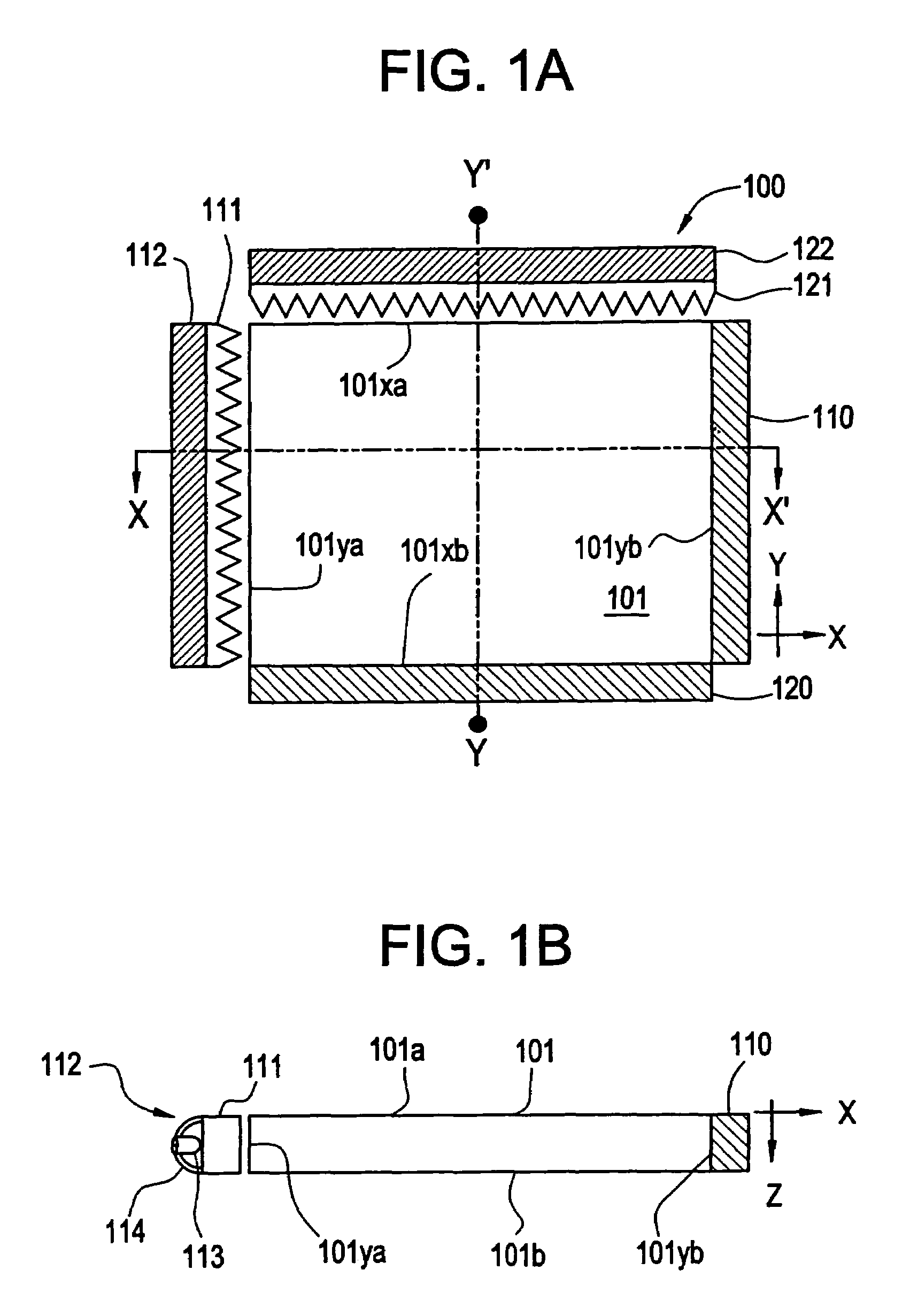
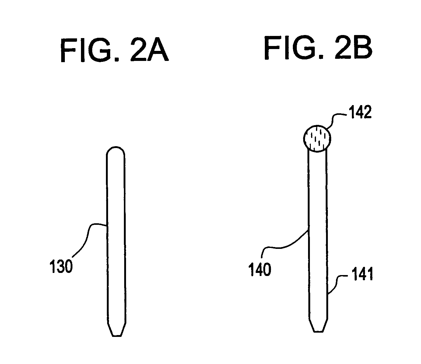
[0028]The first embodiment of this invention is explained in conjunction with FIGS. 1A and 1B, FIGS. 2A and 2B, FIGS. 3A, 3B and 3C.
[0029]FIGS. 1A and 1B show the construction of a touch panel of this invention. FIG. 1A is a top view and FIG. 1B is a cross-sectional view of FIG. 1A taken along a dotted line X-X′. In the touch panel 100 of this invention, a panel surface thereof is formed of a light guide panel 101 which is made of translucent material. On a side face 101yb of the light guide panel 101, an optical sensor array 110 for detecting a position in a Y-axis direction (Y coordinates) is closely mounted. A prism lens sheet 111 is mounted on and along a side face 101ya which opposes the side face 101yb and a light emitting face of the prism lens sheet 111 opposes the side face 101ya. Furthermore, an illumination device 112 is provided such that the device 112 opposes to an incident light face of the prism lens sheet 111.
[0030]The cross-sectional structure of the touch panel 10...
second embodiment
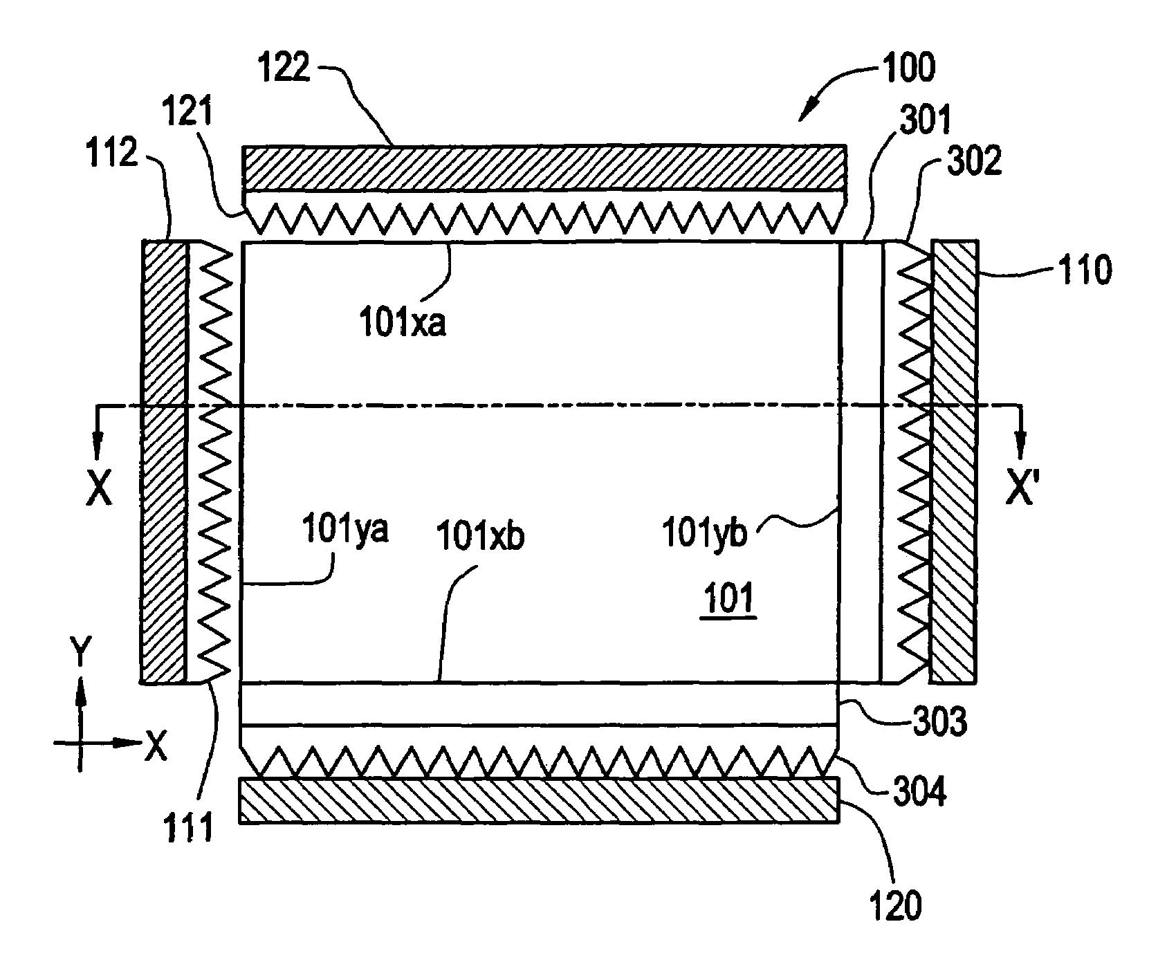
[0060]This embodiment is explained in conjunction with FIGS. 4A and 4B. Same constitutional elements used in FIGS. 1A, 1B, FIGS. 2A, 2B and FIGS. 3A, 3B, 3C are denoted by the same numerals. FIGS. 4A and 4B are composed of views showing the construction of a touch panel of this invention, wherein FIG. 4A is a top view and FIG. 4B is a cross-sectional view of FIG. 4A taken along a dotted line X-X′ of FIG. 4A.
[0061]This embodiment is a modification of the first embodiment. This embodiment is characterized by an improvement that it is constructed such that a light led to a light guide panel 101 is efficiently received by optical sensor arrays 110, 120. That is, a pair of prism lens sheets 301, 302 are inserted between the light guide panel 101 and the optical sensor array 110, while a pair of prism lens sheets 303, 304 are inserted between the light guide panel 101 and the optical sensor array 120.
[0062]The prism lens sheets 301, 303 are closely mounted on the side faces 101yb, 101xb o...
third embodiment
[0067]This embodiment relates to a display device equipped with the touch panel of the first or second embodiment.
[0068]As shown in FIG. 5, the touch panel 100 of this invention is used in such a manner that it is mounted in front of a display screen of a display device such as a crystal display device 400. Since the light guide panel 101 is made of translucent material, the display screen 401 can be seen by way of the light guide panel 101. When one inputs a character or a picture to the touch panel 100 using the input pen 130 while watching the display screen 401, the screen of the crystal display device is changed corresponding to the change of the position of the input pen 130. When inputting is made using the input pen 130 or the fingertip, substantially no deformation occurs on the light guide panel 101 and hence, no physical force is applied to the screen of the crystal display device below the touch panel.
[0069]It is needless to say that as the display device of this embodim...
PUM
 Abstract
Description
Claims
Application Information
 - R&D
- Intellectual Property
- Life Sciences
- Materials
- Tech Scout
- Unparalleled Data Quality
- Higher Quality Content
- 60% Fewer Hallucinations
Browse by: Latest US Patents, China's latest patents, Technical Efficacy Thesaurus, Application Domain, Technology Topic, Popular Technical Reports.
© 2025 PatSnap. All rights reserved.Legal|Privacy policy|Modern Slavery Act Transparency Statement|Sitemap|About US| Contact US: help@patsnap.com


