Laser-induced optical wiring apparatus
a laser-induced optical wiring and wiring technology, applied in the direction of laser details, laser cooling arrangements, optical resonator shape and construction, etc., can solve the problems of increasing the wiring resistance or inter-wiring capacitance, the reproducibility and reliability of conventional techniques such as jp-a h6-132516(kokai) is significantly low, and the process is extremely difficult to realiz
- Summary
- Abstract
- Description
- Claims
- Application Information
AI Technical Summary
Benefits of technology
Problems solved by technology
Method used
Image
Examples
first embodiment
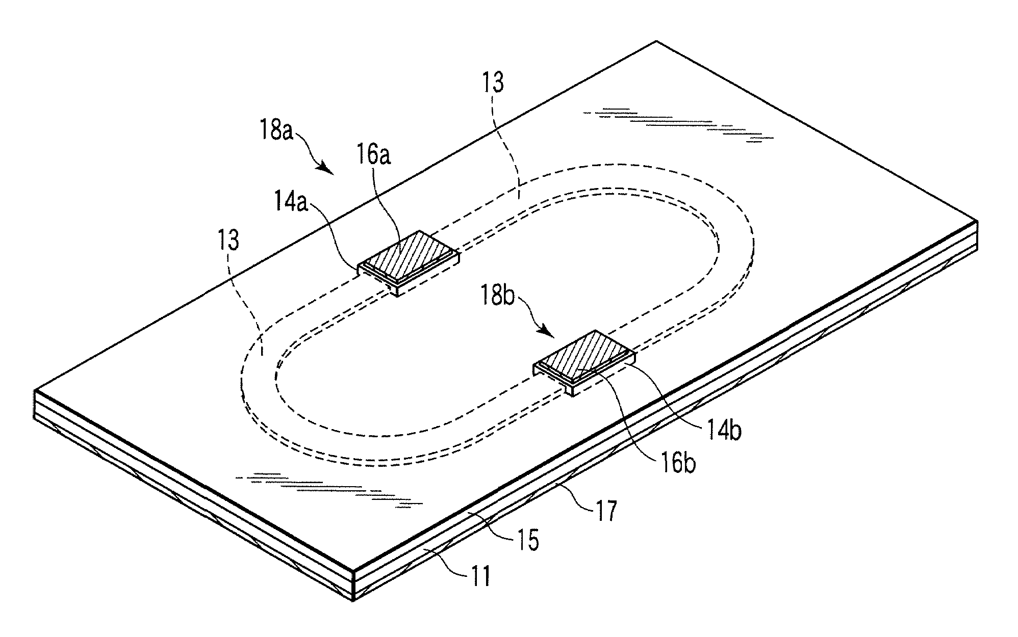
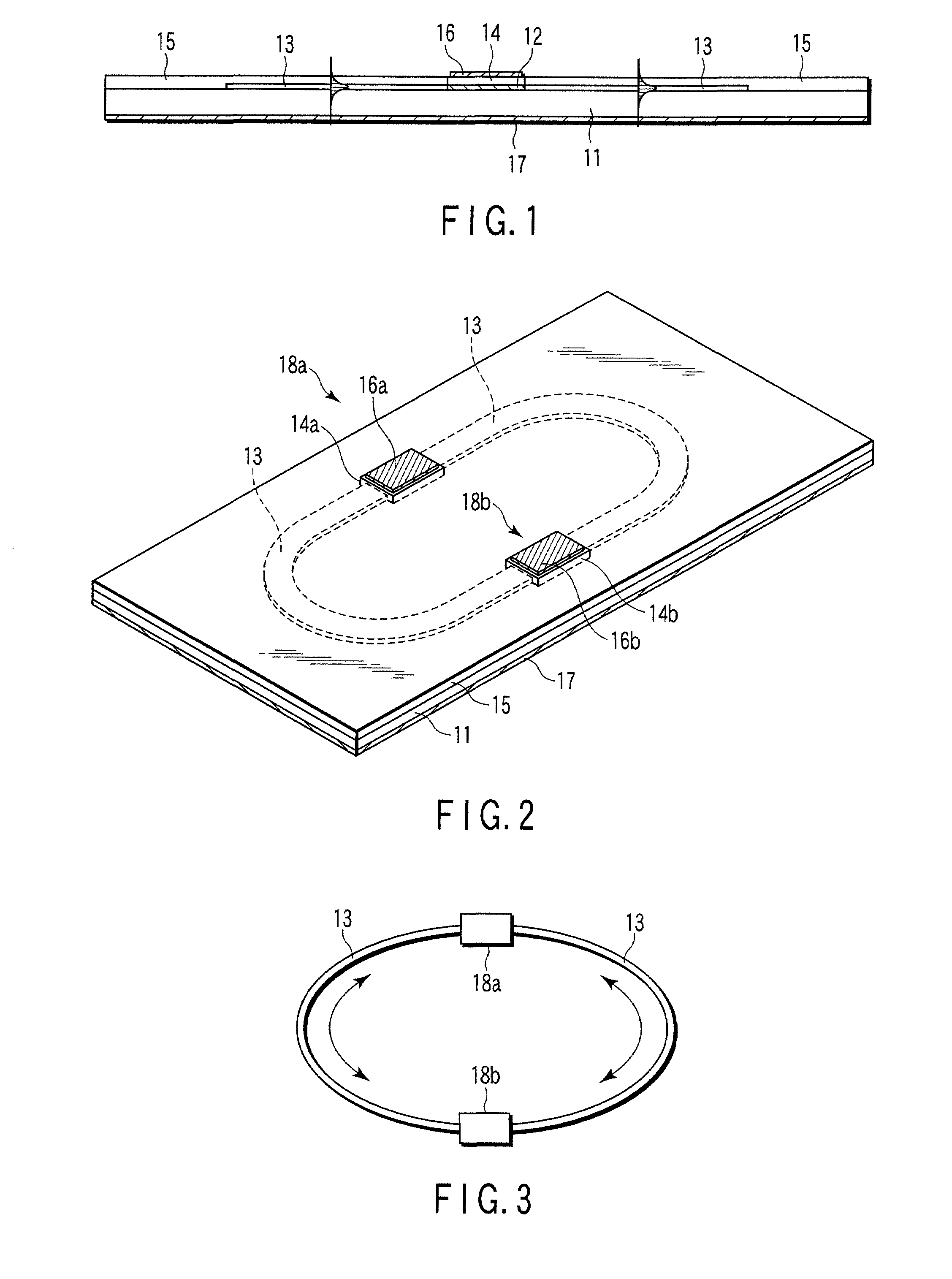
[0044]FIG. 1 is a schematic perspective view illustrating the structure of a laser-induced optical wiring apparatus according to a first embodiment. FIG. 1 shows only elements necessary for optical wiring. Further, FIG. 2 shows the cross section taken along the axis of the apparatus of FIG. 1. Although the first embodiment employs GaInAsP / InP-based materials as material examples of the apparatus, it may employ other materials, such as GaAlAs / GaAs-based materials, Si and SiGe / Si.
[0045]In FIGS. 1 and 2, reference number 11 denotes an n-type InP substrate, reference number 12 denotes a GaInAsP active layer (laser medium having an emission wavelength of 1.3 μm), reference number 13 denotes a GaInAsP optical waveguide core (having, for example, a band gap wavelength of 1.2 μm), reference numbers 14a and 14b denote p-type InP layers, and reference number 15 denotes a semi-insulated clad layer (e.g., an Fe-doped InP layer). Further, reference numbers 16a and 16b denote p-side electrodes (f...
second embodiment
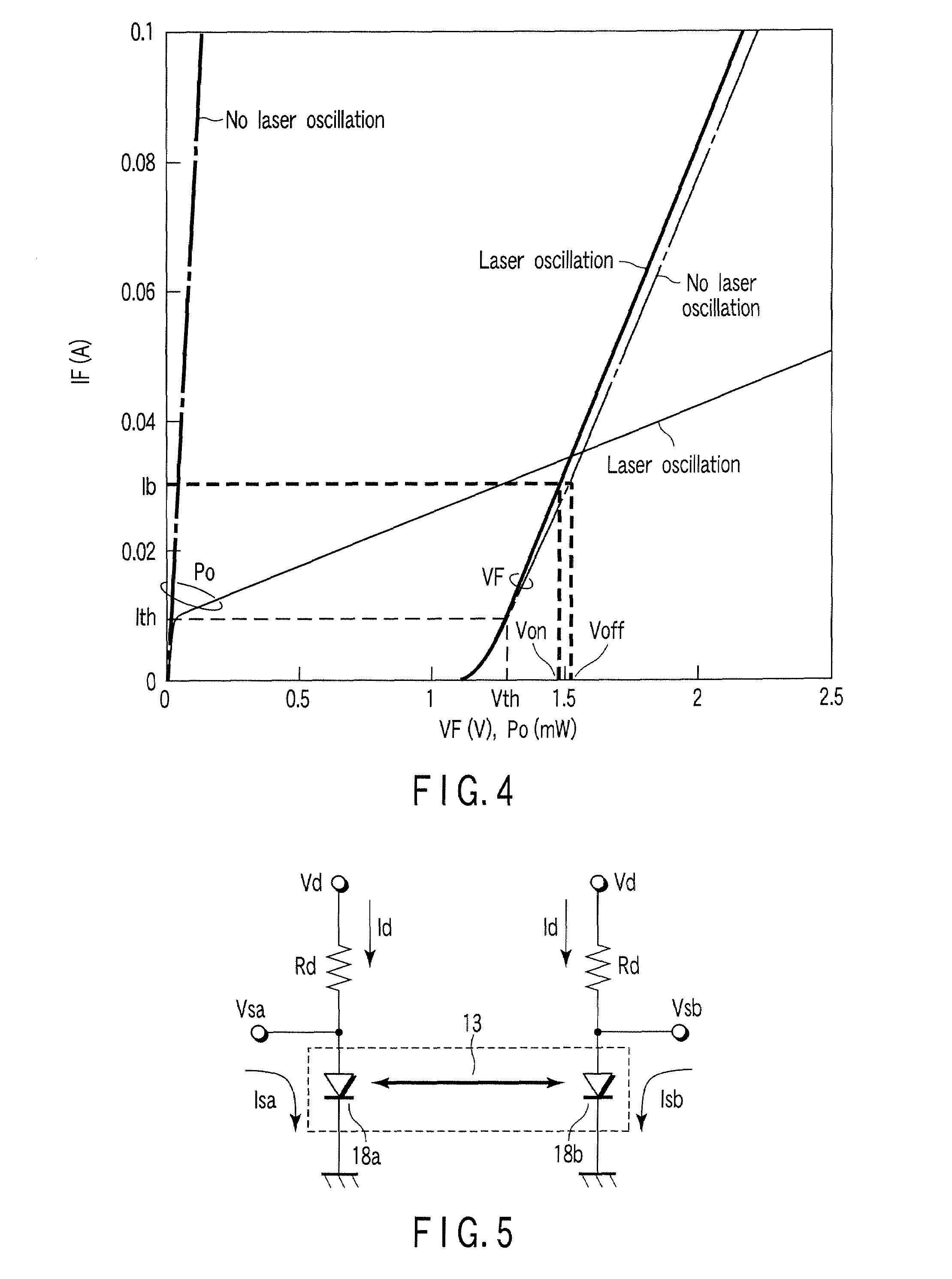
[0069]FIG. 5 shows a laser-induced optical wiring apparatus according to a second embodiment. The second embodiment includes a circuit equivalent to the laser-induced optical wiring apparatus of FIGS. 1 to 3, and a peripheral circuit. However, it should be noted that the method for operating the apparatus is not limited to that described below, like the above-described operation method.
[0070]In FIG. 5, the circuit including the optical gain sections 18a and 18b and optical waveguide core 13 enclosed by the broken line is equivalent to the first embodiment shown in FIGS. 1 to 3. Bias resistors Rd may be located on or outside the substrate of the apparatus of FIG. 1. In the second embodiment, assume that the bias voltage applied to the bias resistor Rd connected in series to the optical gain section 18b is Vd, the bias current flowing through each bias resistor Rd is Id, the voltage applied at the connection terminal between the bias resistors Rd and optical gain sections 18a and 18b ...
third embodiment
[0074]FIG. 6 is a schematic perspective view illustrating the structure of a laser-induced optical wiring apparatus according to a third embodiment. In FIG. 6, elements similar to those of FIG. 2 are denoted by corresponding reference numbers, and no detailed description is given thereof.
[0075]In the first and second embodiments, signal transmission between two points has been described as an example. In the third embodiment, four optical gain sections are provided across the optical waveguide core 13, thereby enabling signal transmission between four points. Specifically, four GaInGsP active layers (not shown), four p-type InP clad layers and four p-type electrodes 16 are provided at four portions of the optical waveguide core 13, thereby providing four optical gain sections 18a, 18b, 18c and 18d.
[0076]The operation principle and method of the third embodiment are similar to those of the signal transmission between two points shown in FIGS. 1 to 5, and laser oscillation is execute...
PUM
 Abstract
Description
Claims
Application Information
 - R&D
- Intellectual Property
- Life Sciences
- Materials
- Tech Scout
- Unparalleled Data Quality
- Higher Quality Content
- 60% Fewer Hallucinations
Browse by: Latest US Patents, China's latest patents, Technical Efficacy Thesaurus, Application Domain, Technology Topic, Popular Technical Reports.
© 2025 PatSnap. All rights reserved.Legal|Privacy policy|Modern Slavery Act Transparency Statement|Sitemap|About US| Contact US: help@patsnap.com


