Magnetostrictive torque sensor

a torque sensor and magnetostrictive technology, applied in the field of magnetostrictive torque sensors, can solve the problems of high impedance state of the output side and easy disturbance, and achieve the effect of suppressing disturbances affecting the output signal, preventing sensitivity reduction of detection signals, and high impedan

Active Publication Date: 2010-02-09
HONDA MOTOR CO LTD
View PDF13 Cites 1 Cited by
  • Summary
  • Abstract
  • Description
  • Claims
  • Application Information

AI Technical Summary

Benefits of technology

[0012]According to the above magnetostrictive torque sensor, when current flows in the direction from one side to another side by the current direction switching device, by detecting the torque based on the output signal of the inversion device, regardless of the ON / OFF switching by the current direction switching device, it is possible to detect the torque based on a constant voltage signal. Therefore, since it is possible to omit a hold circuit, it is possible to prevent sensitivity reduction of the detection signal.
[0013]In addition, when using the hold circuit, the output side becomes high impedance state and susceptible to disturbances. On the other hand, in the present invention, since an output of the detection coil can be output as a constant voltage without a hold circuit, it is not required to endow the output side circuit with high impedance. Consequently, disturbances affecting the output signal can be suppressed.
[0015]In this case, any one of the periods either the period when the current flows in the direction from one side to another side of the detection coil or the period when the current flows in the inverse direction from another side to one side of the detection coil is longer than another period. Therefore, in addition to the previously described advantage described above, it is possible to superimpose a direct current component on the current which flows in the detection coil. Therefore, it is possible to continuously apply a bias magnetic field to the shaft. Consequently, it is possible to apply to act a bias magnetic field that is stronger than the effect of the earth magnetism depending on destinations where magnetic orientations are different on the surface of the earth, for example, in the northern hemisphere or the southern hemisphere. Accordingly, since the direction of the torque which is detected by the detection coil is not inversed by the effect of the earth magnetism, it is possible to detect the torque with higher reliability.

Problems solved by technology

In addition, when using the hold circuit, the output side becomes high impedance state and susceptible to disturbances.

Method used


Image

  • Magnetostrictive torque sensor
  • Magnetostrictive torque sensor
  • Magnetostrictive torque sensor

Examples


Embodiment Construction

[0022]Hereunder is a description of a magnetostrictive torque sensor according to an embodiment of the present invention, with reference to accompanying drawings.

[0023]In this embodiment, one example of a magnetostrictive torque sensor which is used in an electrical power-steering device for a vehicle is explained. Moreover, the electrical power-steering device of the embodiment drives a motor (not illustrated in the FIGURES) based on a detection result of the magnetostrictive torque sensor and applies a predetermined torque to the steering.

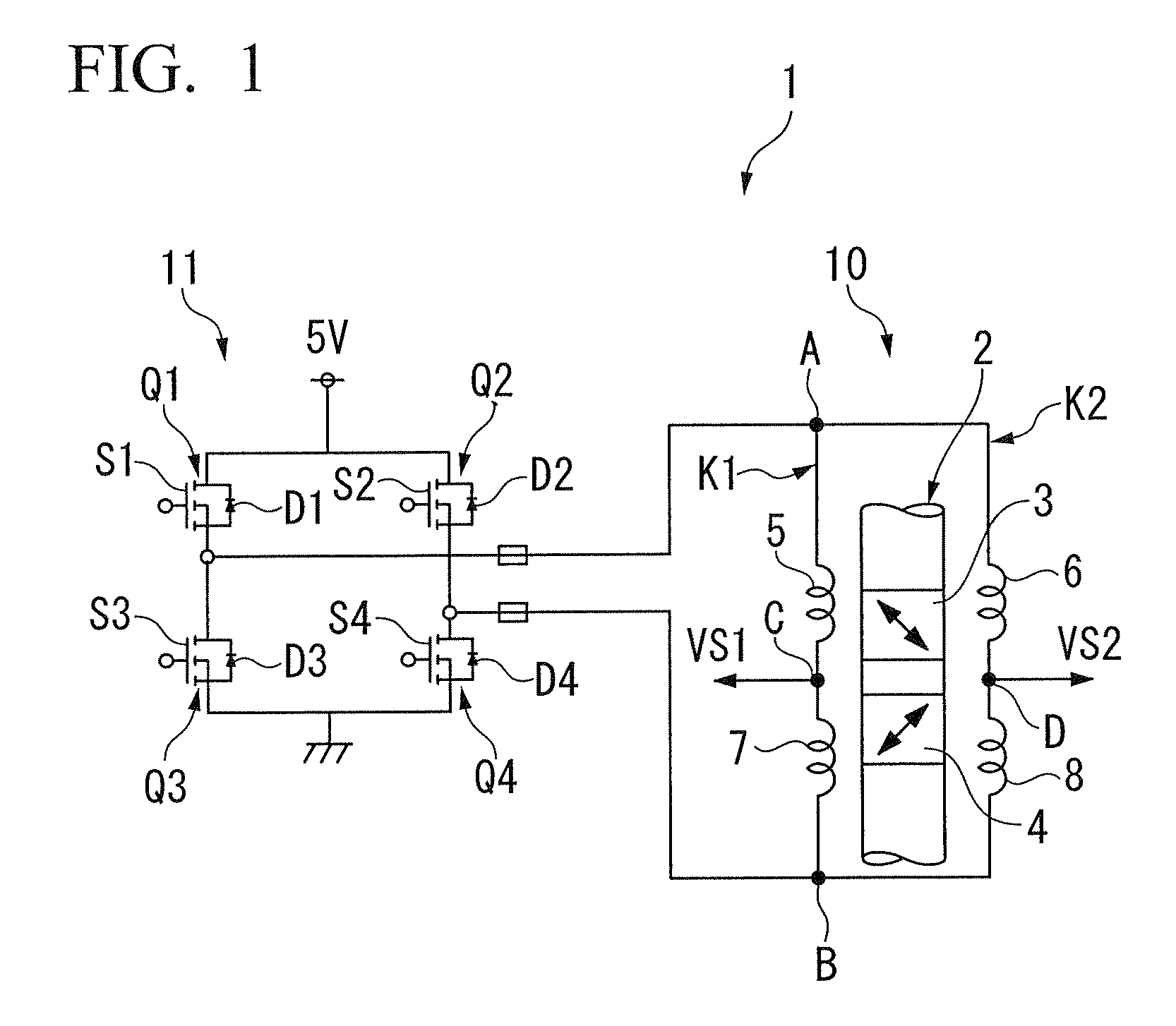
[0024]FIG. 1 shows a magnetostrictive torque sensor 1 used for steering torque detection. The magnetostrictive torque sensor 1 is provided with a first magnetostrictive film 3 and a second magnetostrictive film 4 which are provided on a rotating shaft 2 which is connected to a handle (not illustrated in the FIGURES). The first magnetostrictive film 3 and second magnetostrictive film 4 are arranged respectively in parallel in the direction of the ...


PUM

PropertyMeasurementUnit
electrical source voltageaaaaaaaaaa
voltageaaaaaaaaaa
voltageaaaaaaaaaa

Abstract

A magnetostrictive torque sensor of the present invention is provided with: a magnetostrictive film; a detection coil; a current direction switching device; and an inversion device, wherein: when the current flows in a direction from one side to another side of the detection coil by the current direction switching device, the torque reacted to the shaft is detected based on the input signal of the inversion device; and when the current flows in a inverse direction from another side to one side of the detection coil by the current direction switching device, the torque reacted to the shaft is detected based on the output signal of the inversion device.

Description

BACKGROUND OF THE INVENTION[0001]Priority is claimed on Japanese Patent Application No. 2007-218295, filed on Aug. 24, 2007, the contents of which are incorporated herein by reference.[0002]1. Field of the Invention[0003]This invention is related to a magnetostrictive torque sensor.[0004]2. Description of Related Art[0005]Conventionally, there is known a magnetostrictive torque sensor, which detects a torque acted to the rotating shaft of a steering device of a vehicle, using a magnetostrictive film which has magnetic anisotropy and a coil (for example, refer to Japanese Unexamined Patent Application, First Publication No. 2005-321316).[0006]This magnetostrictive torque sensor repeatedly energizes and disconnects a detection coil by using a switching element, and maintains a voltage between the earths of the detection coils by a peak or trough hold circuit during energization, and detects the torque acted to the shaft based on an output signal of the hold circuit.[0007]However, in t...

Claims


Application Information

Patent Timeline
Patent Type & Authority Patents(United States)
IPC IPC(8): G01L3/10
CPCG01L3/102G01R33/025G01R33/04G01L3/105
Inventor ASAUMI, HISAOHARATA, HITOSHI
Owner HONDA MOTOR CO LTD
Why Eureka
Try Eureka