[0007]The invention aims to provide a movable conveyor belt storage installation and elements suitable therefor, which enable without difficulty its use in particularly low tracks and also the passage of ditches and crowns in the driving operation. The invention further aims to provide a movable conveyor belt storage installation of the initially defined kind, which enables a change from one track to another without requiring the disassembly and reassembly of the conveyor and, in particular, the belt storage means.
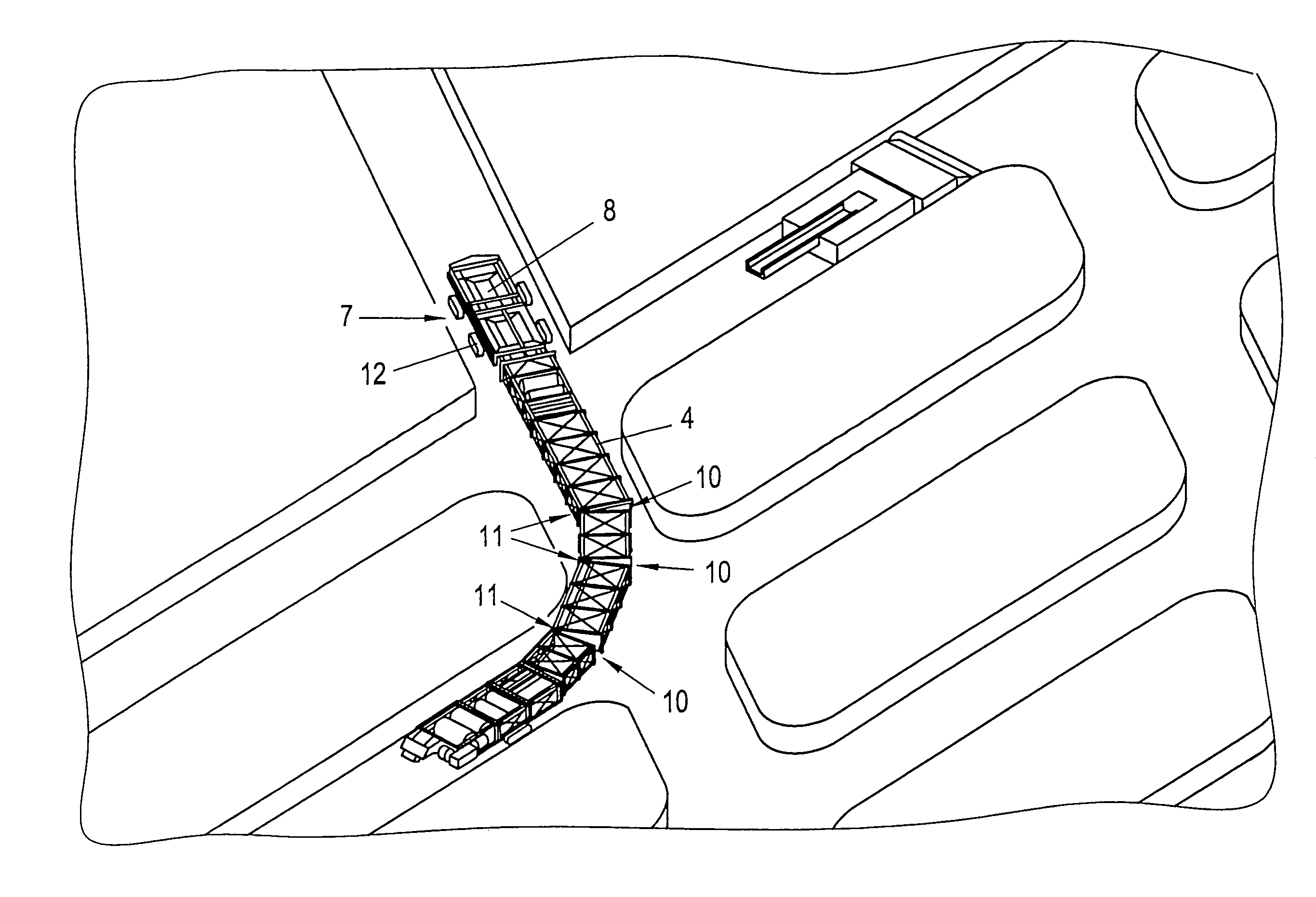
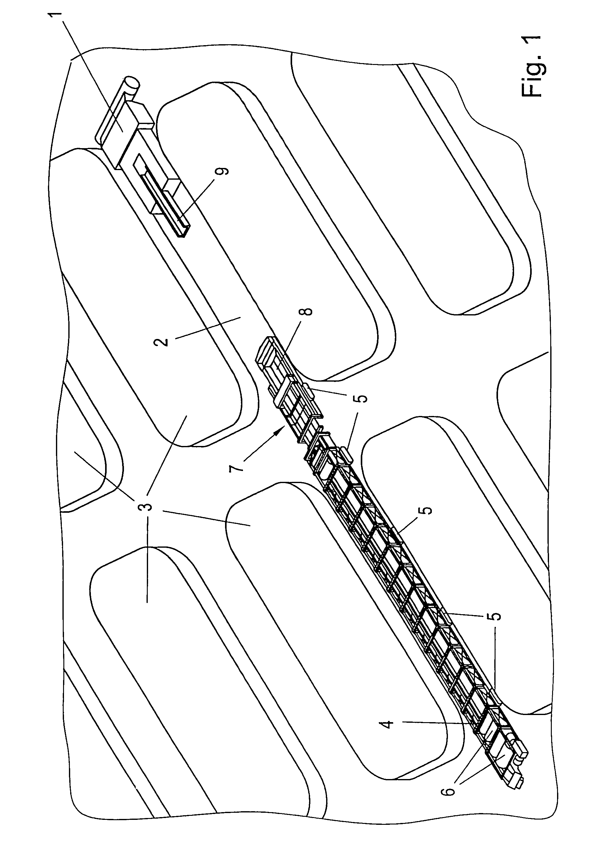
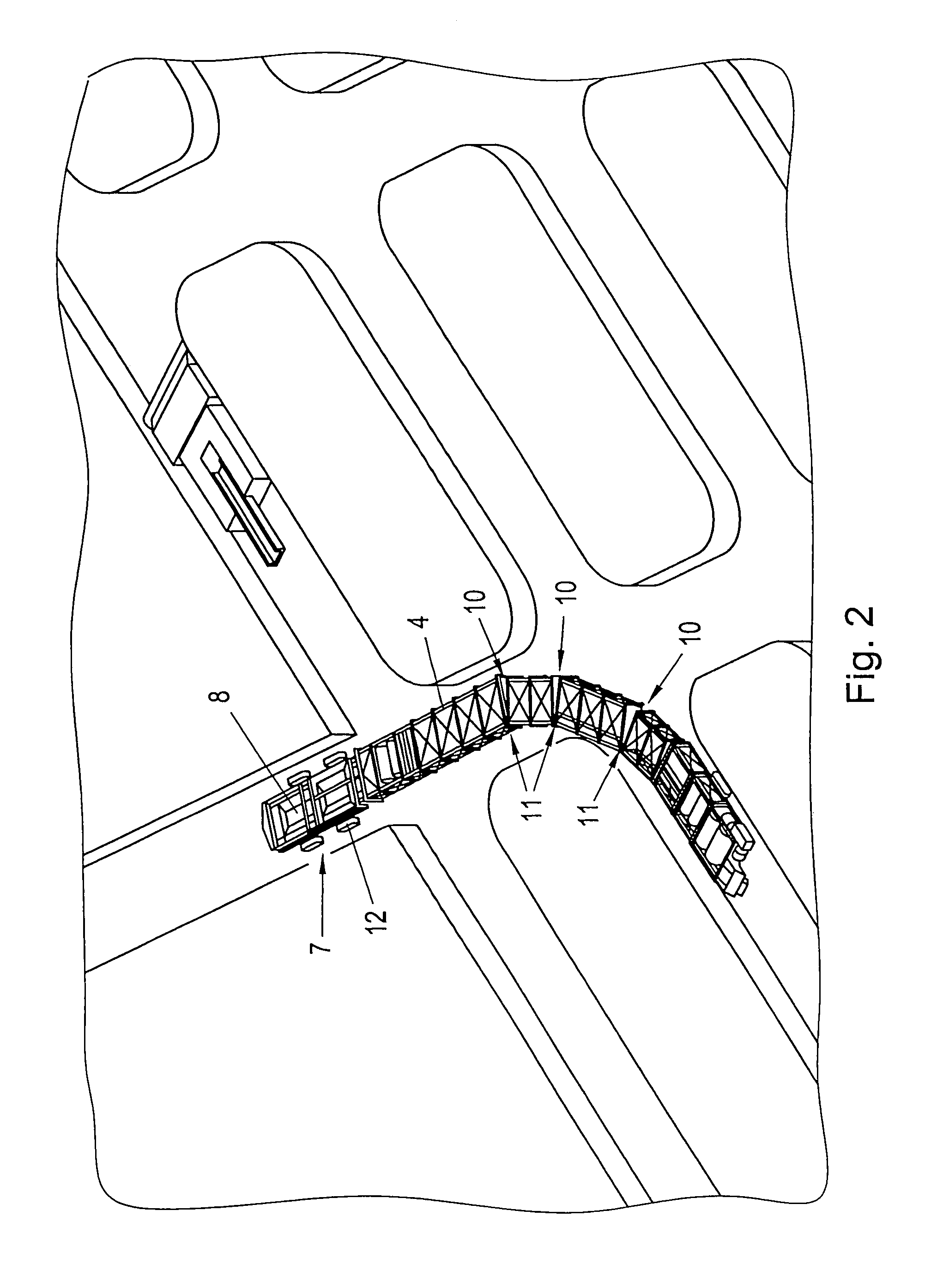
[0008]To solve this object, the movable conveyor belt storage installation according to the invention, of the initially defined kind essentially consist in that the belt storage means is comprised of at least two segments which are connected with one another so as to be pivotable about an axis extending transversely to the belt running direction and passing through the plane of the floor, and that at least a portion of the support structures are capable of being carried along in or on the takeover car. Due to the fact that the belt storage means is comprised of a plurality of segments which themselves are, in turn, articulately connected with one another, and connected with one another so as to be pivotable about an axis extending transversely to the belt running direction and passing through the plane of the floor, it has become feasible to ensure the movability of the overall installation without disassembly of the belt storage means even in narrow curves. By at least a portion of the support structures being capable of being carried along in or on the takeover car, the supports required for an extension of the conveyor belt will always be taken along as far as close to the mine face so as to enable the largely continuous reconstruction of the support in line with the excavation progress without requiring long transport distances for the individual support structures.
[0011]In order to be able to reliably furnish particularly long tracks with conveyor belt, the configuration according to the invention is advantageously devised such that at least one segment comprises bearings for mounting support rollers carrying additional conveyor belt. Additional conveyor belt is, thus, already integrally carried along with the belt storage means on separate reels and, hence, no additional device needs to be employed to extend the conveyor belt. The formation of the belt storage means of individual segments allows for the assignment of such additional functions to individual segments while, nevertheless,
safeguarding the flexibility required for the passage of any tracks.
[0013]The desired all-
terrain-suitability and flexibility with narrow curve radii will advantageously be achieved in that at least three articulately connected segments are each equipped with at least one crawler mechanism. The articulatability in any direction will be ensured in a particularly simple manner in that the articulately connected segments each comprise two independently operable locking members arranged outside the longitudinal center of the belt storage means or the respective segment, and that the segments are each connected with one another so as to be pivotable about the locked axis, with the respectively locked curve-inner axis ensuring the respective pivotability. Locking, or the release of locking, can be effected in a particularly simple manner in that the locking members are formed by hydraulically actuatable pins, whereby such a configuration will also ensure that accordingly high forces will be safely absorbed by the locking members.
[0014]The takeover car that is particularly suitable for use in the movable conveyor belt storage installation according to the invention comprises, like other known cars, a frame and a
chassis connected with the frame, particularly a crawler mechanism, and a deflection
pulley for a conveyor belt running below a takeup chute, and additionally, according to the invention, further elements and is preferably further developed such that the frame is configured as a
portal frame to articulately support at least one
subframe for holding carrying structures and / or a bearing of the deflection
pulley and / or the takeup chute. The configuration of the frame as a
portal frame allows for the suspension of the
subframe in a suitable manner and, in particular, its fixation in an accordingly resilient fashion in the manner of a three-point bearing so as to enable self-adjustment of the conveyor belt via the deflection
pulley. At the same time, such a suspension allows for an enhanced mobility in ditches and an easier passage of crowns in the driving operation, since the use of a
subframe enables the achievement of an appropriate height adjustability relative to the
portal frame in order to avoid collisions with the floor. In this respect, the configuration is advantageously devised such that the subframe is suspendingly mounted on the portal frame, wherein the subframe is preferably connected with the portal frame so as to be adjustable in the height direction.
[0016]For the safe mounting of the support structures entrained by the takeover car as far as close to the mine face, the configuration is advantageously devised such that the subframe comprises beams extending in the longitudinal direction of the takeover car for accommodating support structures, wherein a deposit for connection rods for the support structures is advantageously provided in addition, which connection rods are connectable with two locking sites of the support structures via at least two locking members, in particular screw bolts, which are offset in the longitudinal direction over the connection rods. The provision of at least two locking sites arranged to be offset in the longitudinal direction allows for the
interconnection of the individual supports with a view to securing them against tilting or pivoting, so that space-demanding bottom plates can be obviated and an increased number of supports can be readily carried along by the takeover car. The configuration in this respect is advantageously devised such that the support structures are mounted on the subframe via rollers so as to be displaceable in the longitudinal or conveying direction.

