Tool having damper

a technology of damper and tool, which is applied in the direction of shock absorbers, manufacturing tools, mechanical equipment, etc., can solve the problems of tool damage or breakage, deterioration of surface roughness or size accuracy, and easy generation of vibration of spherical material, so as to improve the degree of freedom in designing the damper, optimize and manufacture the damper, and accurately adjust the damping characteristics of the relative movement

Inactive Publication Date: 2010-02-16
HITACHI TOOL ENG LTD
View PDF22 Cites 30 Cited by
  • Summary
  • Abstract
  • Description
  • Claims
  • Application Information

AI Technical Summary

Benefits of technology

[0014]Therefore, the present invention has been made in view of the above problems, and it is an object of the present invention to provide the structure of a damper, which is mounted in a tool, that is capable of improving the degree of freedom in design to optimize the damping characteristics of the damper and can also be suitably used in multi-product and small-quantity production applications, and a manufacturing method using the same.
[0015]It is another object of the present invention to provide the structure of a damper that is capable of allowing the damper to be easily optimized and manufactured for a wide variety of dynamic stiffness characteristics of a tool body, and a manufacturing method using the same.
[0018]According to the present invention, hermetically-sealed annular spaces are formed as a part of the damper, and a viscous fluid is filled in the annular spaces. As a result, it is possible to accurately adjust the damping characteristics of the relative movement of the weight part with respect to the tool body by changing the thickness of the viscous fluid layer. Consequently, the degree of freedom in designing the damper is improved for various tools having different sizes and shapes. Also, it is possible to optimize and manufacture the damper for specific dynamic stiffness characteristics of the tool body. Consequently, even when the stiffness of the spindle of a machine tool is different, it is possible to easily design and manufacture an appropriate damper, and therefore, it is possible to easily prevent the generation of chatter vibrations. Furthermore, the present invention can be easily applied to multi-product and small-quantity production applications.

Problems solved by technology

As a result, chatter vibrations are easily generated, the surface roughness or the accuracy in size is deteriorated, and the tool is damaged or broken.
In these methods, it may be required to form, with high accuracy, grooves or holes, in which the material, such as cemented carbide, is added, and therefore, the manufacturing costs may be increased.
Also, it is possible to change the natural frequency by improving the spring constant; however, the damping due to the friction at the connection part is not very large, and therefore, desired vibration prevention is not obtained.
In these methods, the tool body is maintained in a natural frequency mode; however, the natural frequency mode is denied by the dynamic damper, and therefore, the vibration amplitude is decreased.
As a result, the vibrations are damped.
In the dynamic damper, the optimum value of the viscous resistance with respect to the movement of the weight part exists, and therefore, it is not possible to obtain the function as the damper when the viscous resistance is too large or too small.
Consequently, in the case that normal silicon oil is used as the viscous fluid, there are frequent occasions when the viscous resistance is too large, or there are frequent occasions when the gap must be large.
For this reason, this method is not suitable for multi-product and small-quantity production applications in which multi-purpose tools are manufactured.
However, a material, such as tungsten, is very expensive.
As a result, it is not reasonable to manufacture a plurality of weight parts having different inner diameters in the case that the damper is produced on a large scale.
For this reason, this method is also not suitable for multi-product and small-quantity production applications in which multi-purpose tools are manufactured.
Also, in the case that the tool body, in which the dynamic damper is mounted, is long, and the mass of the tool body is large, like a long tool, the vibrations of the tool body are easily damped when the mass of the weight part mounted in the tool body is also large.
However, the amount of change is not very large, and therefore, it is also possible to decrease the sectional area of the ring-shaped elastic members.
As a result, it is difficult to adjust the natural frequency of the weight part.

Method used


Image

  • Tool having damper
  • Tool having damper
  • Tool having damper

Examples


Embodiment Construction

[0034]First, a tool, having a damper mounted therein, according to preferred embodiments of the present invention will be described in brief.

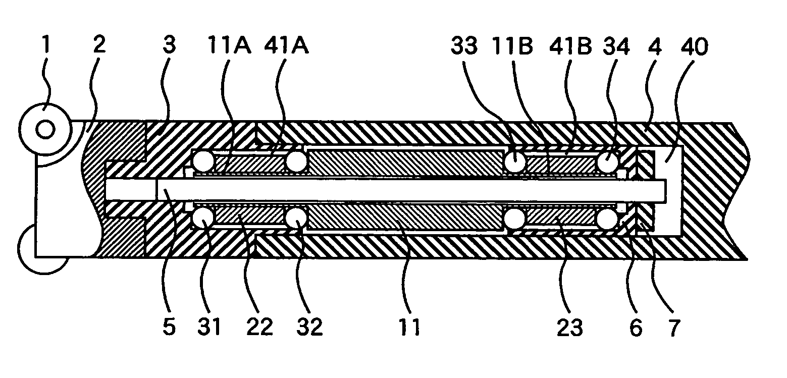
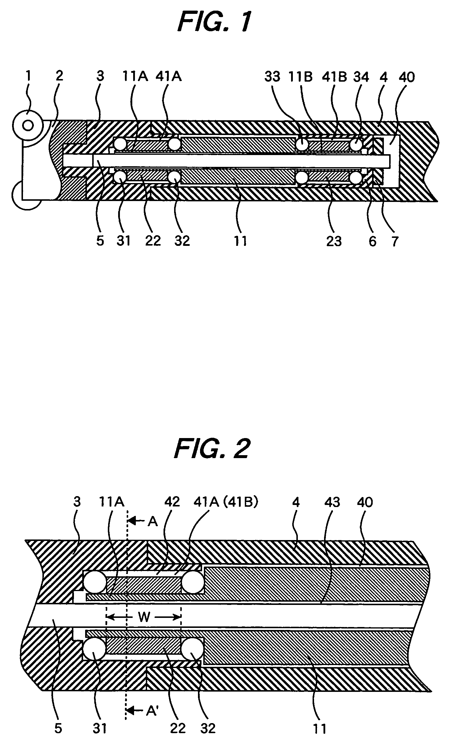
[0035]According to the preferred embodiments of the present invention, there is provided a tool having a damper wherein a hollow part is formed in a tool body such that the hollow part extends in the axial direction, and a weight part, which is substantially formed in the shape of a cylinder, is mounted in the hollow part such that the weight part can be moved relative to the tool body. At opposite ends of the weight part, which are opposite to each other in the axial direction, are formed annular spaces, which are hermetically sealed. The annular spaces are filled with a viscous fluid. More specifically, a plurality of ring-shaped elastic members are mounted in the annular spaces, and the viscous fluid is filled in the region surrounded by the outer circumferential surface of the weight part, the inner surface of the tool body, and the plurali...


PUM

PropertyMeasurementUnit
lengthsaaaaaaaaaa
lengthsaaaaaaaaaa
lengthsaaaaaaaaaa

Abstract

Disclosed herein is the structure of a damper that is capable of improving the degree of freedom in design to optimize the damping characteristics of the damper and is capable of allowing the damper to be easily optimized and manufactured for a wide variety of dynamic stiffness characteristics of a tool body, and a manufacturing method using the same. A plurality of ring-shaped elastic members are disposed at opposite ends of a weight part. The weight part is connected to the tool body via the elastic members. Consequently, the weight part is moved relative to the tool body. The plurality of elastic members are mounted while spacers are disposed between the elastic members, and the spacers are moved with respect to the weight part in the axial direction thereof. A viscous fluid is filled in the region surrounded by the outer circumferential surfaces of the spacers, the elastic members, and the inner surface of a hollow part of the tool body. Consequently, it is possible to damp the relative movement of the weight part with respect to the tool body.

Description

FIELD OF THE INVENTION[0001]The present invention relates to a tool having a damper and a cutting method using the same, and, more particularly, to a long tool attached in a cutting tool or a workpiece for preventing the generation of chatter vibrations when a cutting process is carried out using a machine tool, and a cutting method using the same.BACKGROUND OF THE INVENTION[0002]During an inner boring process using a lathe, a boring process using a machining center, or a process using an endmill or a milling cutter is performed, a narrow part or a deep hole part is processed using a long tool, the protruding size of which is relatively large as compared to the total size of the tool. At this time a boring bite or a milling cutter is attached to the tip end of the tool. For this reason, the stiffness at a holder of the cutting tool is lowered as the length of the holder is increased. As a result, chatter vibrations are easily generated, the surface roughness or the accuracy in size ...

Claims


Application Information

Patent Timeline
Patent Type & Authority Patents(United States)
IPC IPC(8): B23B47/00
CPCB23B29/022B23C5/003B23C5/10Y10T408/76Y10T409/304312
Inventor ONOZUKA, HIDEAKITAKAHASHI, HAYATOKATOU, TOMU
Owner HITACHI TOOL ENG LTD
Why Eureka
Try Eureka