Audio-to-video synchronization system and method for packet-based network video conferencing

a video conferencing and audio-to-video technology, applied in the field of multimedia communication systems, can solve the problems of adding an appreciable overhead, not being able to synchronize streams based on an accurate clock time, and not inherently providing real-time communication in packet networks

Inactive Publication Date: 2010-02-16
CISCO TECH INC
View PDF9 Cites 80 Cited by
  • Summary
  • Abstract
  • Description
  • Claims
  • Application Information

AI Technical Summary

Benefits of technology

[0013]The present invention overcomes the disadvantages of prior art synchronization systems by synchronizing streams without reference to an external clock. For the example of an IP switched network using RTP, the present

Problems solved by technology

Packet networks thus do not inherently provide real-time communication.
While the use of a reference time to synchronize clocks to provide signal synchronization across a network is effective, this method has several problems.
If NTP is not working when requested

Method used


Image

  • Audio-to-video synchronization system and method for packet-based network video conferencing
  • Audio-to-video synchronization system and method for packet-based network video conferencing
  • Audio-to-video synchronization system and method for packet-based network video conferencing

Examples


first embodiment

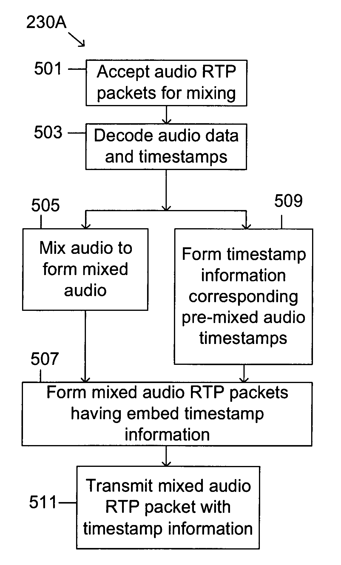
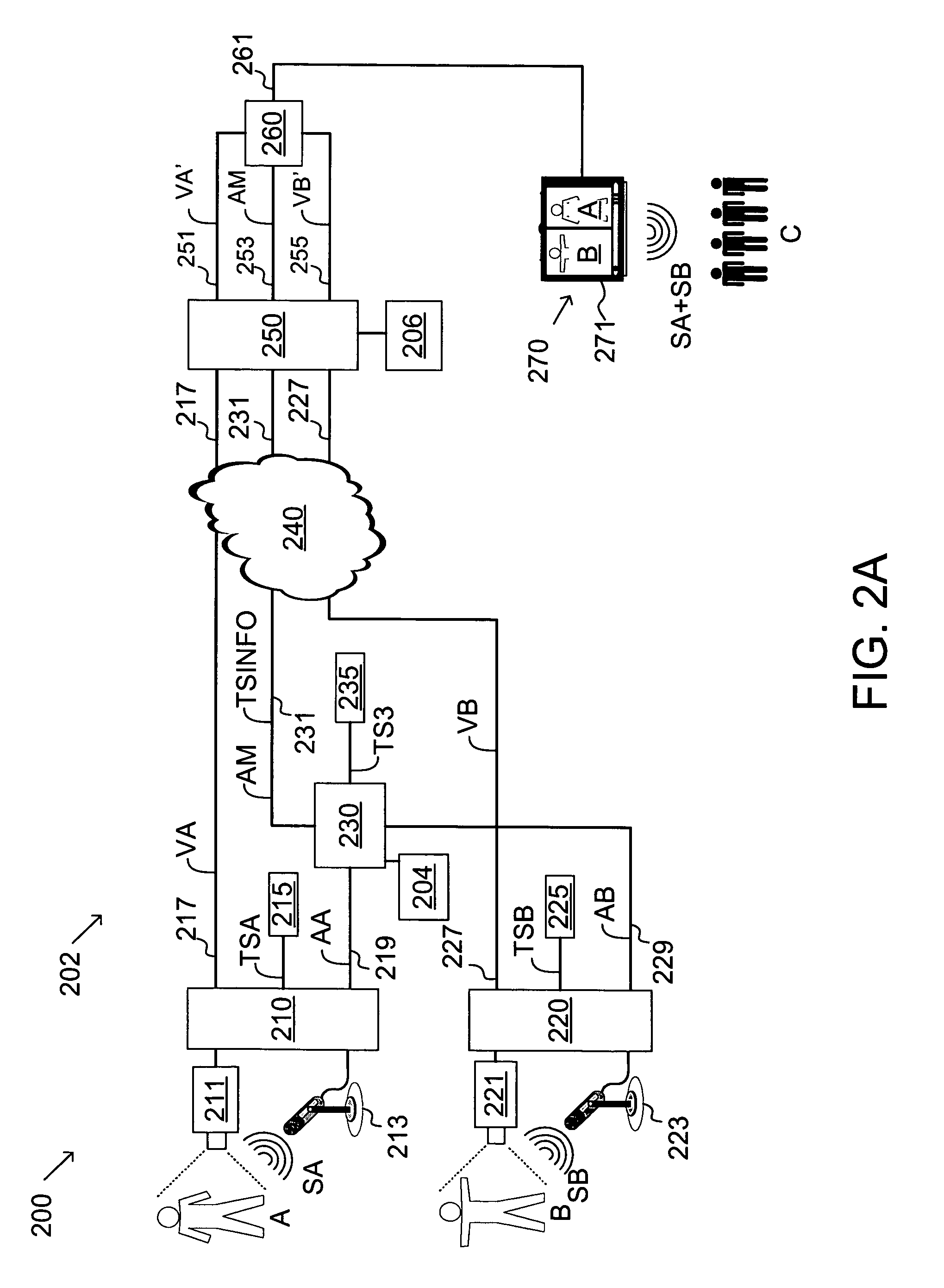
[0065]The use of the above equations will be used to illustrate specific embodiments of the present invention without limiting the scope of the present invention. FIG. 3A is a schematic of a first embodiment synchronizing packet network 202A of the present invention for implementing the system of FIG. 2A, including an ingress-mixer 230A having an ingress 311A and a mixer 309, and a synchronizer-egress 250A having a timestamp stripper 301A, a timestamp memory 303, a video A synchronizer 305, a video B synchronizer 307, and a synchronization buffer 308. FIGS. 4A and 4B illustrate two RTP packet embodiments AM+TSINFO, and FIGS. 5A and 5B, are flow charts of steps performed by ingress-mixer 230A and synchronizer-egress 250A, respectively.

[0066]The operation of packet network 202A in updating video streams VA and VB with timestamps synchronized with mixed audio stream AM is illustrated in the flowcharts of FIGS. 5A and 5B. RTP packets containing audio from streams AA and AB are accepted ...

second embodiment

[0076]A second embodiment synchronizing packet network is illustrated in the FIG. 3B as a schematic of network 202B of the present invention including an ingress-mixer 230B having an ingress 311B and a mixer 309, and a corresponding synchronizer-egress 250B having a timestamp stripper 301B, a timestamp memory 303, a video A synchronizer 305, a video B synchronizer 307, and a synchronization buffer 308. FIG. 4C illustrates an RTP packet embodiments, and FIGS. 6A and 6B, are flow charts of steps performed by ingress-mixer 230B and synchronizer-egress 250B, respectively.

[0077]The embodiment of FIG. 3B differs from that of FIG. 3A in that timestamp information TSINFO is sent in packets different than the AM data. Thus, for example, the data packets shown in FIG. 4C include shows as a mixed audio RTP packet AM and a separate timestamp information RTP packet TSINFO. Both AM and TSINFO packets are sent from the ingress point to the egress point, as explained subsequently. In an alternative...

third embodiment

[0080]FIG. 7 is a schematic of a third embodiment synchronizing packet network 202C in which synchronization occurs separately from egress. Network 202C has terminals 210 and 220 and ingress-mixer 230 connected through a first WAN network 703 to a synchronizer 701, whose operation is shown in the flowchart of FIG. 8, and a composer 260, and further connected through a second WAN network 705 to a synchronizer-egress 250 to a terminal 270.

[0081]Network 202C illustrates the use of timestamp information TSINFO at different network locations. In particular, the operation of synchronizer 701 is similar to synchronizer-egress 250, except that it does not perform the egress function of removing of timestamp information. As shown in FIG. 8, synchronizer 701 includes a block 801 the provides mixed audio RTP packets without stripping TSINFO, since TSINFO is required by synchronizer-egress 250 to synchronize the streams after leaving second network 705. Synchronizer 701 also includes the steps ...


PUM


Abstract

Synchronizing audio and video streams in packet-based networks requires synchronization of packet timestamps. The present invention provides such synchronization without resort to a network time standard. In one embodiment of the present invention, pairs of timestamp synchronized signals, such as audio and video signals, not having a common timestamp clock are mixed. One of the signals, for example, the audio signals, is mixed first while preserving the original audio timestamps. The preserved timestamp information is then used to synchronize the timestamps of the unmixed signals, in this example the video signals, to provide synchronization of all signals. In another embodiment, the present invention uses packets containing calibration of timestamps to reduce jitter. The present invention also includes specifications for a packet for transmitting timestamp information.

Description

BACKGROUND OF THE INVENTION[0001]This invention is related to multimedia communications systems, and in particular to a method of synchronizing audio and video streams over a packet network without relying on a network time standard.BACKGROUND[0002]Multimedia multipoint conferences, commonly called multimedia teleconferences, are becoming more widespread. A multimedia teleconference allows three or more participants at a plurality of locations to establish bi-directional multimedia communication in a shared audio-visual environment that gives the impression that the participants are all at the same place.[0003]Packet-based networks, and in particular IP-based packet networks, are being used with increasing popularity for multimedia conferences. Packet-based networks (also referred to herein as “packet networks”) provide communication between network locations by transmitting as a sequence of individual, timestamped packets. The transmission of individual packets between two network ...

Claims


Application Information

Patent Timeline
IPC IPC(8): H04L12/16G06F15/16H04Q11/00H04L12/66H04J3/06H04J3/16H04J3/22H04J3/24
CPCH04N21/234318H04N21/2368H04N21/4307H04N21/4341H04N21/8547H04L65/607H04L65/608H04L65/80H04L69/28H04Q2213/13034H04Q2213/13214H04Q2213/13337H04Q2213/1336H04Q2213/13389H04N21/43072H04L65/65H04L65/70
Inventor WU, FANGCHEN, WEN-HSIUNGFRIEDRICH, WALTER R.SARKAR, SHANTANU
Owner CISCO TECH INC
Why Eureka
Try Eureka