Steam trap monitoring

a technology for monitoring and steam traps, applied in the direction of testing/monitoring control systems, process and machine control, instruments, etc., can solve the problems of steam traps that are completely mechanical, add any electrical wiring for power or monitoring, and are considered cost prohibitive. , the problem of steam traps experiencing a very common problem

Active Publication Date: 2010-02-16
ROSEMOUNT INC
View PDF32 Cites 15 Cited by
  • Summary
  • Abstract
  • Description
  • Claims
  • Application Information

AI Technical Summary

Problems solved by technology

Often, steam traps are completely mechanical.
Adding any electrical wiring for either power or monitoring would be considered cost prohibitive, impractical and / or labor intensive.
Steam traps experience a very common problem; they often leak.
Steam trap leakage is often due to wear of the movable member within the steam trap, deterioration or fouling of the valve (s), or a number of other reasons.
Regardless of the cause, steam trap leakage is undesirable for a number of reasons.
First, it takes a relatively large amount of energy to heat water into steam.
Further, many condensate removal systems are not designed for continuous pressurization, such as that caused by a steam leak.
Accordingly, the component(s) downstream from a steam trap could be damaged, or otherwise degraded, by a continuous steam leak.
Finally, given a sufficient leak, the steam pipe may not be able to supply sufficient steam pressure and flow to achieve its desired purpose.

Method used


Image

  • Steam trap monitoring
  • Steam trap monitoring
  • Steam trap monitoring

Examples


Embodiment Construction

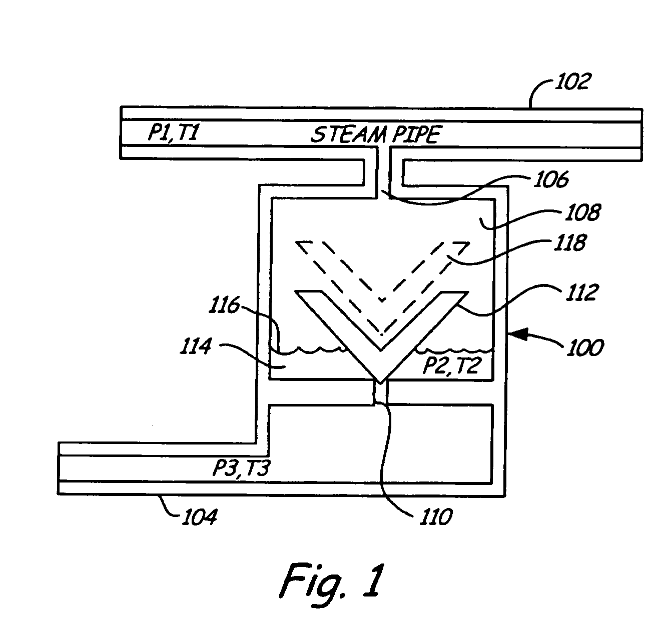
[0013]Embodiments of the present invention can be practiced with respect to any steam trap that has an inlet that is coupled, or couplable, to a steam pipe, and an outlet that periodically releases condensate and / or air, but otherwise is expected to maintain an elevated pressure with respect to the ambient environment.

[0014]FIG. 1 is a diagrammatic view of a steam trap with which embodiments of the present invention are useful. Steam trap 100 is fluidically coupled to steam pipe 102 and water collection / return line 104. Steam pipe 102 has steam disposed therein at first pressure (P1) and first temperature (T1). The steam may be static or flowing, and may be saturated steam or superheated steam. Condensate flowing, or otherwise present within steam pipe 102 will flow into inlet 106 and accumulate in the chamber 108. Chamber 108 includes an outlet port 110 that is closed or occluded by movable member 112. Movable member 112 may comprise a baffle or any other suitable physical structur...


PUM


Abstract

Electronic steam trap monitoring is disclosed. An electronic steam trap monitor is operably coupled to an outlet of a steam trap and is configured to measure at least one process variable of fluid (liquid or gas) flowing through the trap, when the trap is known to be working normally. The steam trap monitor stores the process variable information obtained during the known operating condition for later comparison. The steam trap monitor obtains a later process variable measurement and compares it to the stored measurement to selectively generate a leakage indication. The steam trap monitor preferably uses a local power source and communicates wirelessly.

Description

BACKGROUND OF THE INVENTION[0001]The present invention is related to the monitoring of steam traps. More particularly, the present invention is related to a system and method for detecting a leak in a steam trap.[0002]Steam traps are commonly used in many industries to remove unwanted air and condensate from steam lines. In a typical plant, thousands of such devices may be deployed. A steam trap is generally a relatively low technology device that is designed to be relatively inexpensive. Often, steam traps are completely mechanical. Adding any electrical wiring for either power or monitoring would be considered cost prohibitive, impractical and / or labor intensive.[0003]A steam trap is generally designed to allow condensate to escape a pipe in order to maintain efficiency and reduce pipe “knocking.” A typical steam trap may have one or more chambers and a member that is in physical contact with the condensate. As the level of the condensate rises above some threshold, the movable me...

Claims


Application Information

Patent Timeline
Patent Type & Authority Patents(United States)
IPC IPC(8): G06F3/00
CPCG05B23/0232
Inventor ANDERSON, WILLIAM T.SIERRA, GABRIEL L.BROWN, GREGORY C.
Owner ROSEMOUNT INC
Why Eureka
Try Eureka