Check patentability & draft patents in minutes with Patsnap Eureka AI!

Shared hole orthogonal footprints

a technology of orthogonal holes and shared holes, applied in the direction of connection contact material, coupling device connection, manufacturing tools, etc., can solve the problems of unsatisfactory electrical signal interference between differential signal pairs of electrical contacts, crosstalk, increase, etc., and achieve the effect of improving the performance of an electrical connector

Inactive Publication Date: 2010-02-23
FCI AMERICAS TECH LLC
View PDF13 Cites 10 Cited by
  • Summary
  • Abstract
  • Description
  • Claims
  • Application Information

AI Technical Summary

Benefits of technology

This configuration significantly reduces near-end crosstalk, allowing only far-end crosstalk to be considered, thereby enhancing signal integrity and connector performance, especially in applications where lower total far-end crosstalk is crucial, such as in IEEE 802.3ap links.

Problems solved by technology

Undesirable electrical signal interference between differential signal pairs of electrical contacts (i.e., crosstalk) increases as signal density increases, particularly in electrical connectors that are devoid of metallic crosstalk shields.
Additionally, near-end crosstalk, which may be higher in the connector than far-end crosstalk, may negatively affect the signal integrity of the connector by affecting the far-end crosstalk of the connector.

Method used


Image

  • Shared hole orthogonal footprints
  • Shared hole orthogonal footprints
  • Shared hole orthogonal footprints

Examples


Embodiment Construction

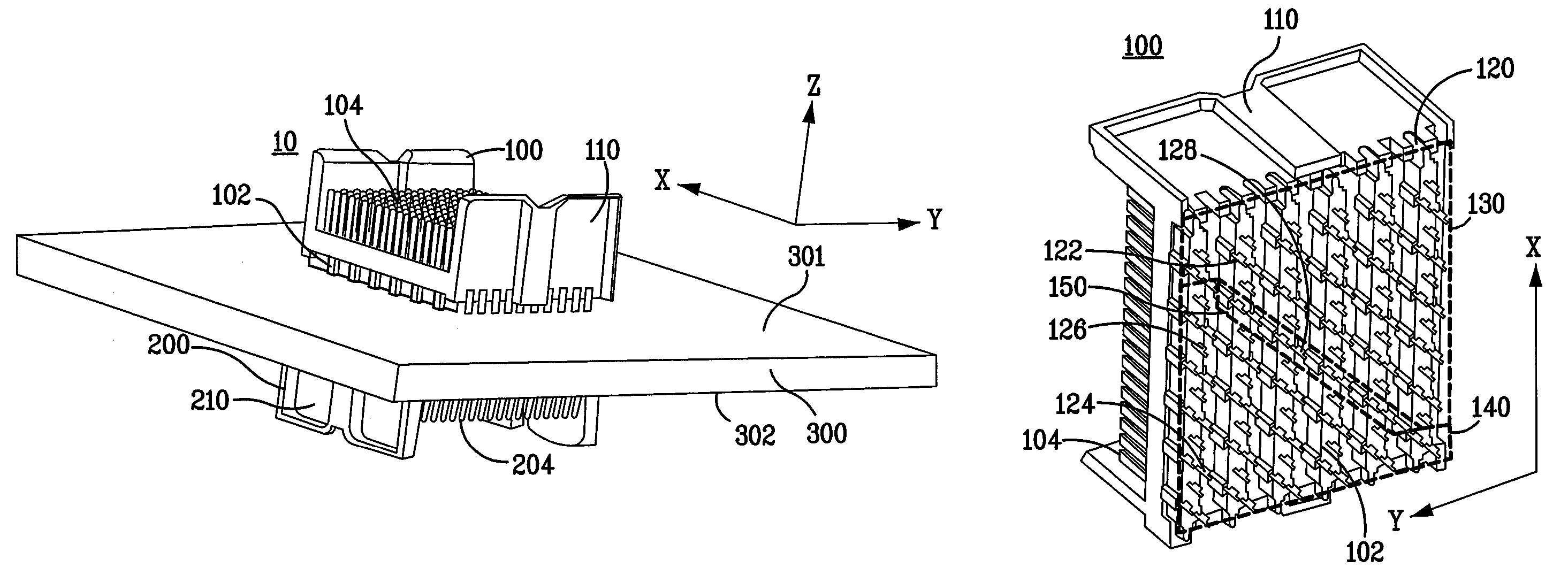
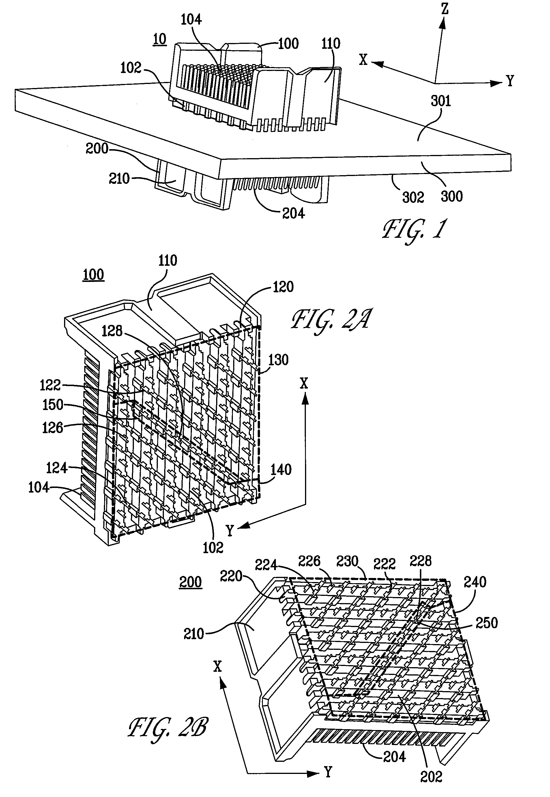
[0018]FIG. 1 is a perspective view of two example orthogonal connectors mounted orthogonally to one another through the use of shared apertures in a midplane. Referring to FIG. 1, an example electrical connector system 10 includes a first electrical connector 100, a second electrical connector 200, and a midplane 300. The first electrical connector 100 defines a mounting interface 102 (for example, for electrical connection to a substrate or any electrical device) and a mating interface 104 (for example, for electrical connection to another electrical connector or any electrical device) and includes a leadframe housing 110. The second electrical connector 200 defines a mounting interface 202 (as shown in FIG. 2B) (for example, for electrical connection to a substrate or any electrical device) and a mating interface 204 (for example, for electrical connection to another electrical connector or any electrical device) and includes a leadframe housing 210. The midplane 300 defines a fir...


PUM

PropertyMeasurementUnit
electrical signalsaaaaaaaaaa
electricalaaaaaaaaaa
signal densityaaaaaaaaaa

Abstract

Disclosed are an electrical connector and a method for providing transmit and receive electrical signal contacts to reduce or minimize total crosstalk. Such methods may be particularly suitable for connectors having larger near-end crosstalk aggressors than far-end crosstalk aggressors. The electrical signal contacts may be subdivided on a substrate, such as a midplane PCB, and through the opposing connectors, such that the transmitting contacts are all on one side of the connector and the receiving contacts are on the other side of the connector, with a buffer between them. The buffer may comprise a plurality of “dummy” or “buffer” contacts, which may be unassigned or devoid of electrical connectivity. This is one step beyond the primary assignment of contacts as single-ended or differential signal contacts. The contacts themselves may also receive a secondary assignment according to their desired transmitting, receiving, or buffering function.

Description

CROSS-REFERENCE TO RELATED APPLICATIONS[0001]This application claims benefit under 35 U.S.C. §119(e) of provisional U.S. patent application No. 61 / 027,182, filed Feb. 8, 2008, the contents of which are incorporated herein by reference in their entirety.FIELD OF THE INVENTION[0002]Generally, the invention relates to electrical connectors. More particularly, the invention relates to assigning transmit and receive signal pairs to reduce or minimize total crosstalk.BACKGROUND OF THE INVENTION[0003]Undesirable electrical signal interference between differential signal pairs of electrical contacts (i.e., crosstalk) increases as signal density increases, particularly in electrical connectors that are devoid of metallic crosstalk shields. Additionally, near-end crosstalk, which may be higher in the connector than far-end crosstalk, may negatively affect the signal integrity of the connector by affecting the far-end crosstalk of the connector.[0004]Therefore, there is a need to reduce the af...

Claims


Application Information

Patent Timeline
Patent Type & Authority Patents(United States)
IPC IPC(8): H01R4/66H01R12/51H01R12/58H01R12/71
CPCH01R13/443H01R13/6471H01R13/6587Y10S439/941Y10T29/532H01R12/716H01R24/62H01R12/712
Inventor MINICH, STEVEN E.KOLIVOSKI, CHRISTOPHER J.SMITH, STEPHEN B.OLEYNICK, GARY J.
Owner FCI AMERICAS TECH LLC
Features
  • R&D
  • Intellectual Property
  • Life Sciences
  • Materials
  • Tech Scout
  • Unparalleled Data Quality
  • Higher Quality Content
  • 60% Fewer Hallucinations
Learn More