
Energy storage system with ultracapacitor and switched battery

a technology of energy storage system and switched battery, which is applied in the field of vehicle energy storage system, can solve the problems of affecting battery life, substantially increasing cost, and high switching load current i/sub>l /sub>, and achieves relatively low non-tractive electrical loads, reduce battery cycling, and reduce discharge.

Active Publication Date: 2010-02-23
TOLEDO UNVERSITY OF THE +1
View PDF14 Cites 16 Cited by
  • Summary
  • Abstract
  • Description
  • Claims
  • Application Information

AI Technical Summary

Benefits of technology

The invention is an energy storage system for a hybrid electric vehicle that reduces battery cycling and extends battery life. It uses an ultracapacitor and a battery in parallel to handle different types of loads during operation. The ultracapacitor is designed to handle high-current surges, while the battery is designed to handle longer-duration loads. The system also includes a battery-charging circuit that selectively connects the battery to the ultracapacitor for charging. The invention also features a separate electrical bus for low-power loads and a bleed circuit to dissipate charge. Overall, the system improves the vehicle's efficiency and performance.

Problems solved by technology

As a result, the batteries experience very high and frequent surge currents and, therefore, must withstand thousands of deep charge / discharge cycles which can potentially impact battery life.
Further, such batteries must be optimized for high-power capability, generally resulting in a substantially increased cost.
However, the foregoing also confirms that the parallel-coupled ultracapacitor and battery results in a battery current iB portion of the switched load current IL being very high, particularly with increasing ambient temperature.
And, while the ultracapacitor generally has very high immunity to high discharge and regenerative pulses such as vehicle start / acceleration pulses and regenerative braking, known chemical batteries typically do not share such a high immunity, and such shared pulses can therefore cause significant degradation of the parallel-coupled batteries due to battery cycling.

Method used


Image

  • Energy storage system with ultracapacitor and switched battery
  • Energy storage system with ultracapacitor and switched battery
  • Energy storage system with ultracapacitor and switched battery

Examples


Embodiment Construction

[0024]The following description of the preferred embodiment(s) is merely exemplary in nature and is in no way intended to limit the invention, its application, or uses.

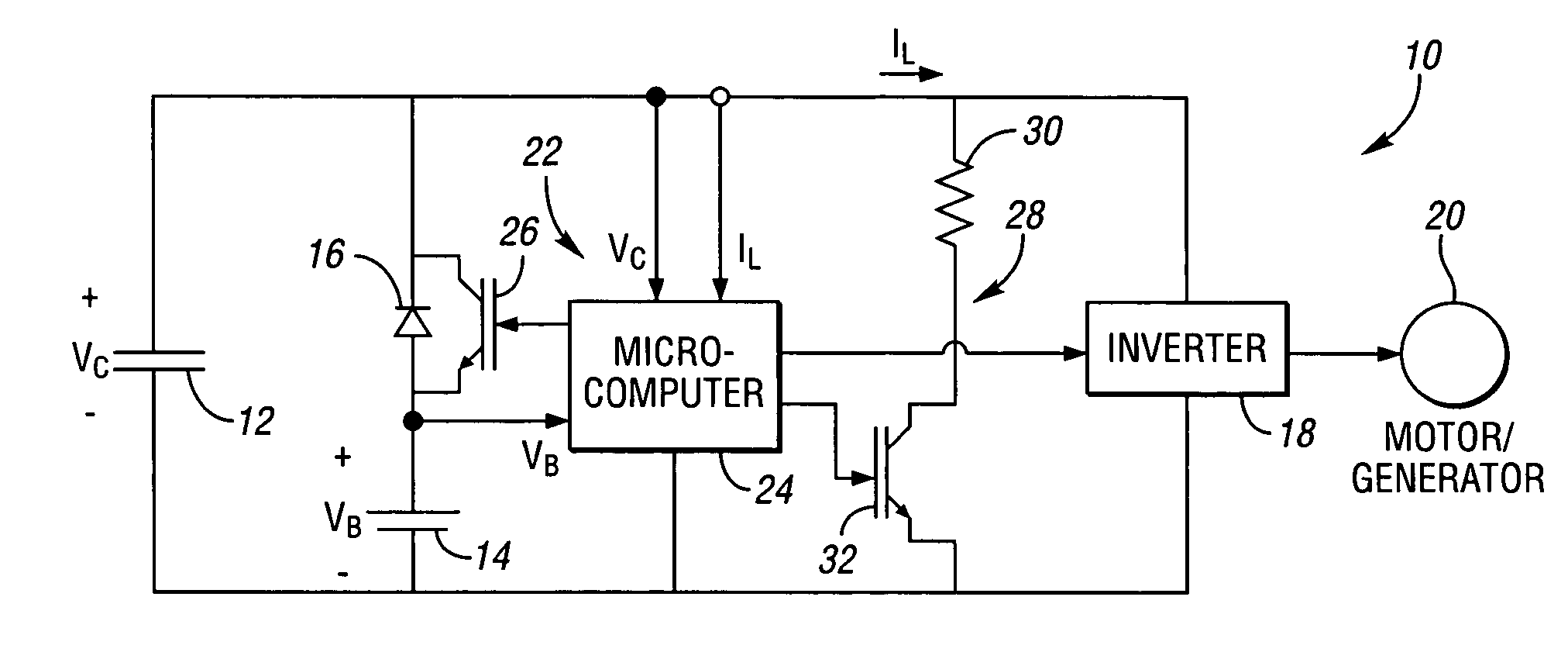
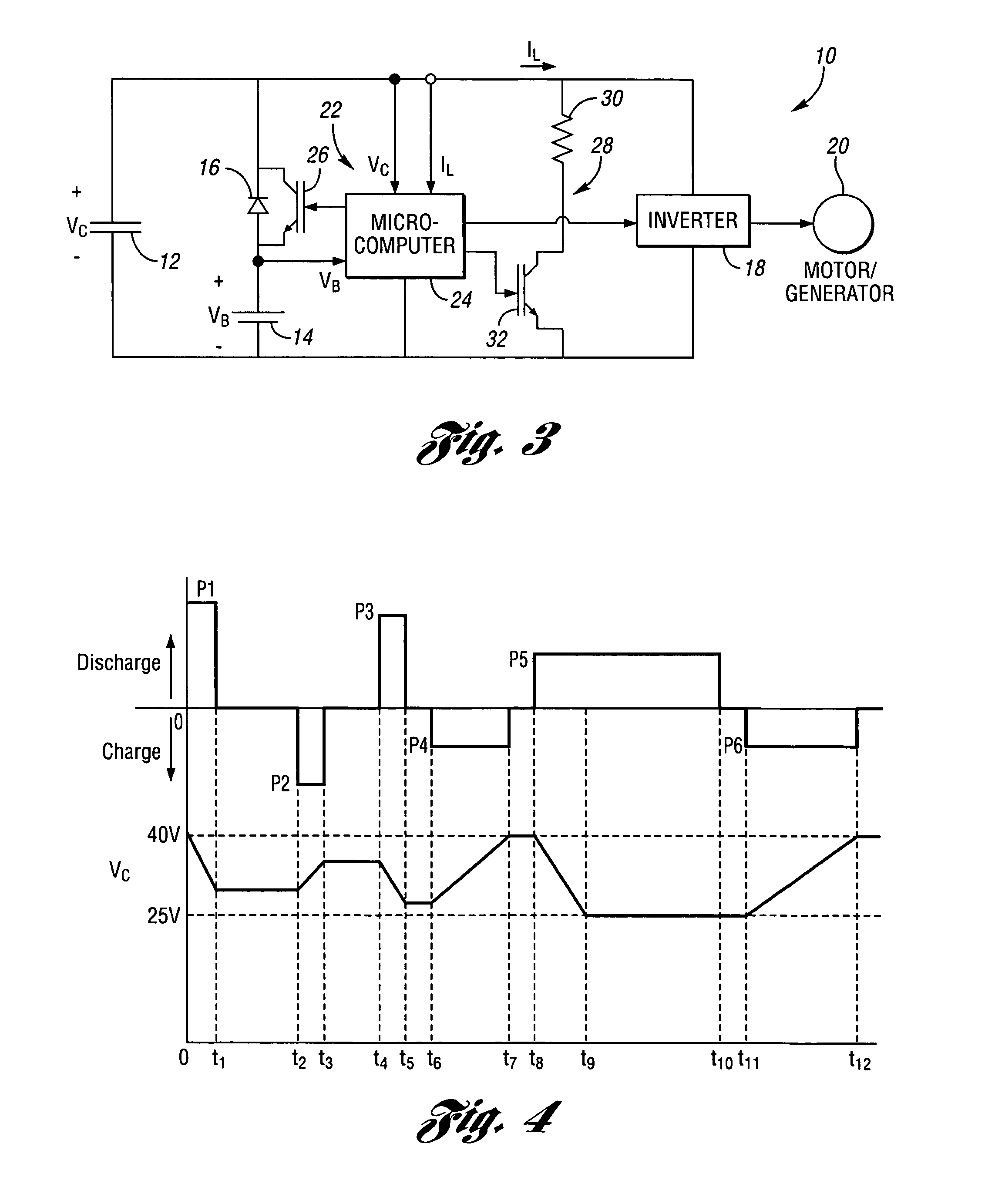
[0025]Referring to the circuit diagram shown in FIG. 3, an exemplary energy storage system10 in accordance with the invention, for use in a hybrid electric vehicle, includes an ultracapacitor 12, and a battery 14 that is electrically coupled in parallel with the ultracapacitor 12 through a series-connected diode 16. For purposes of the invention, the term “ultracapacitor” encompasses electrostatic multiple-layer capacitors (singly or in parallel and / or series combinations), as well as capacitors (single capacitors or parallel and / or series combinations of capacitors) with capacitances above 1 F. It will be appreciated that, when multiple series-connected ultracapacitors are used, the energy storage system preferably includes charge-balancing circuitry (not shown) to prevent against inadvertent overcharging of a given ...


PUM


Abstract

An energy storage system for a vehicle includes an ultracapacitor that is electrically coupled in parallel with a battery through a diode connected in series with the battery. The ultracapacitor delivers the energy required for all high current surges that occur during engine start, acceleration, and regeneration. The battery is used only to assist with longer duration, high energy loads, such as accessory loads when an engine of the vehicle is not running. In other words, the battery conducts only during longer and less-frequent pulses and, therefore, does not have to withstand high-power pulses.

Description

CROSS-REFERENCE TO RELATED APPLICATIONS[0001]This application claims benefit of U.S. provisional patent application No. 60 / 626,560 filed Nov. 10, 2004, the disclosure of which is hereby incorporated by reference.FIELD OF THE INVENTION[0002]The invention relates generally relates to vehicle energy storage systems, particularly energy storage systems suitable for use in hybrid electric vehicles.BACKGROUND OF THE INVENTION[0003]Hybrid electric vehicles (HEVs), whose operation is characterized by both discharge and regenerative tractive electrical loads and nontractive electrical loads, often employ batteries to provide energy boost or storage for short periods such as acceleration, engine start-up, and regenerative braking, as well as for relatively-longer-duration discharge pulses. As a result, the batteries experience very high and frequent surge currents and, therefore, must withstand thousands of deep charge / discharge cycles which can potentially impact battery life. Further, such ...

Claims


Application Information

Patent Timeline
Patent Type & Authority Patents(United States)
IPC IPC(8): H02J7/00
CPCB60K6/28B60W10/26H01G9/155H01G9/26H01M16/00B60W20/00Y02E60/13Y02T10/6278Y02T10/7022B60Y2400/114Y02T10/62Y02T10/70H01G11/08B60W20/13
Inventor ASHTIANI, CYRUS NSTUART, THOMAS A
Owner TOLEDO UNVERSITY OF THE
Learn More