Beverage vending machine installation

Inactive Publication Date: 2010-03-02
KRAFT FOODS R & D INC
View PDF27 Cites 15 Cited by
  • Summary
  • Abstract
  • Description
  • Claims
  • Application Information

AI Technical Summary

Benefits of technology

[0005]Advantageously, the beverage vending machine installation of the present invention may be installed in a wide variety of locations since no access is required to the rear of the cabinet either in use or during maintenance procedures. As a result, the vending machine installation may be installed hard up against a solid wall and there is no requirement to provide a room or other void space directly behind the cabinet. Thus, floor space is saved. Further, providing the vending machine on a trolley unit which may be uninstalled from the cabinet advantageously allows for much easier access to the components of the vending machine to carry out maintenance procedures. In addition, locating the vending machine on a trolley unit allows different vending machine assemblies to be quickly and easily swapped in and out of a single cabinet. For example, a defective vending machine may be easily removed and replaced with a working vending machine allowing the vending machine installation to be used by customers whilst the defective machine is repaired away from the installation.
[0008]Preferably, the trolley unit comprises a load-bearing framework. The framework preferably comprises one or more guide bars and the cabinet comprises a guide frame, wherein on movement of the trolley unit from the uninstalled position into the installed position the guide bars and guide frame interact to locate the trolley unit relative to the cabinet. The interaction between the guide frame and the trolley framework ensures that the trolley unit is accurately and positively located when installed within the cabinet. It also makes the installation process simpler by allowing the installer to simply push the trolley unit inwards; the lateral location of the trolley unit is controlled by the guide frame.
[0010]Preferably, the cabinet comprises one or more ports for the conveyance of utilities and the trolley comprises one or more sockets for the reception of utilities wherein the ports and sockets are connectable in use by means of one or more conduits. The utilities may comprise one or more utilities selected from the group of electricity, telephone and mains water. A particular advantage of the present installation is that the trolley unit and cabinet and only a small number of connections therebetween. In one embodiment the cabinet and trolley unit are connected only by a mains water conduit and a mains electricity cable. Both connections may be provided with bayonet fittings, plugs or similar to allow the connections to be quickly and easily made and broken. This allows the trolley unit to be very quickly installed and removed from the cabinet.
[0021]The present invention also provides a beverage vending machine installation comprising a primary beverage preparation machine, a secondary beverage preparation machine, a customer interface, a telemetry device, and a system controller, wherein the system controller monitors and controls operation of the primary and secondary beverage preparation machines, the customer interface and the telemetry device, wherein the system controller further collates operational information from the primary and secondary beverage preparation machines and transmits said data to a secure site using the telemetry device. Advantageously, the single system controller collates and transmits data to the secure site for multiple elements of the installation. This allows equipment to be easily added or removed or interchanged within the installation without requiring additional telemetry devices to be fitted.

Problems solved by technology

A problem with known vending machine installations is that locating the installation in this way makes ready access to the rear of the cabinet difficult.
A disadvantage of this solution is that extra floor space is taken up by the room or corridor behind the cabinet.
However, this has a disadvantage that the vending machine and its associated equipment within the cabinet can be difficult to access for maintenance purposes, even where the cabinet is accessed from the rear.
In particular, portions of the vending machine and ancillary equipment located on the lateral sides of the units are difficult to access due to the close proximity of other equipment and walls within the cabinet.

Method used


Image

  • Beverage vending machine installation
  • Beverage vending machine installation
  • Beverage vending machine installation

Examples


Embodiment Construction

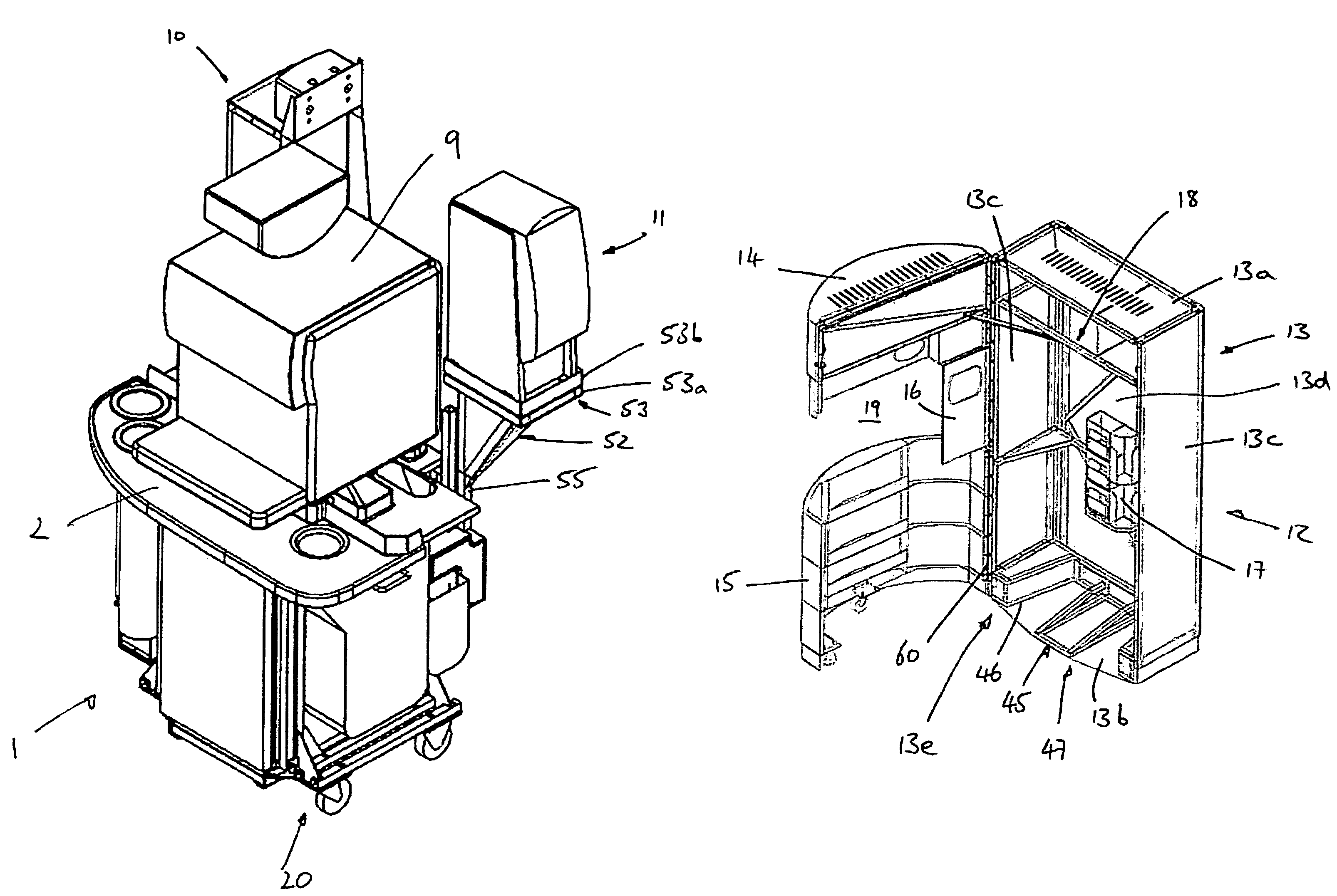
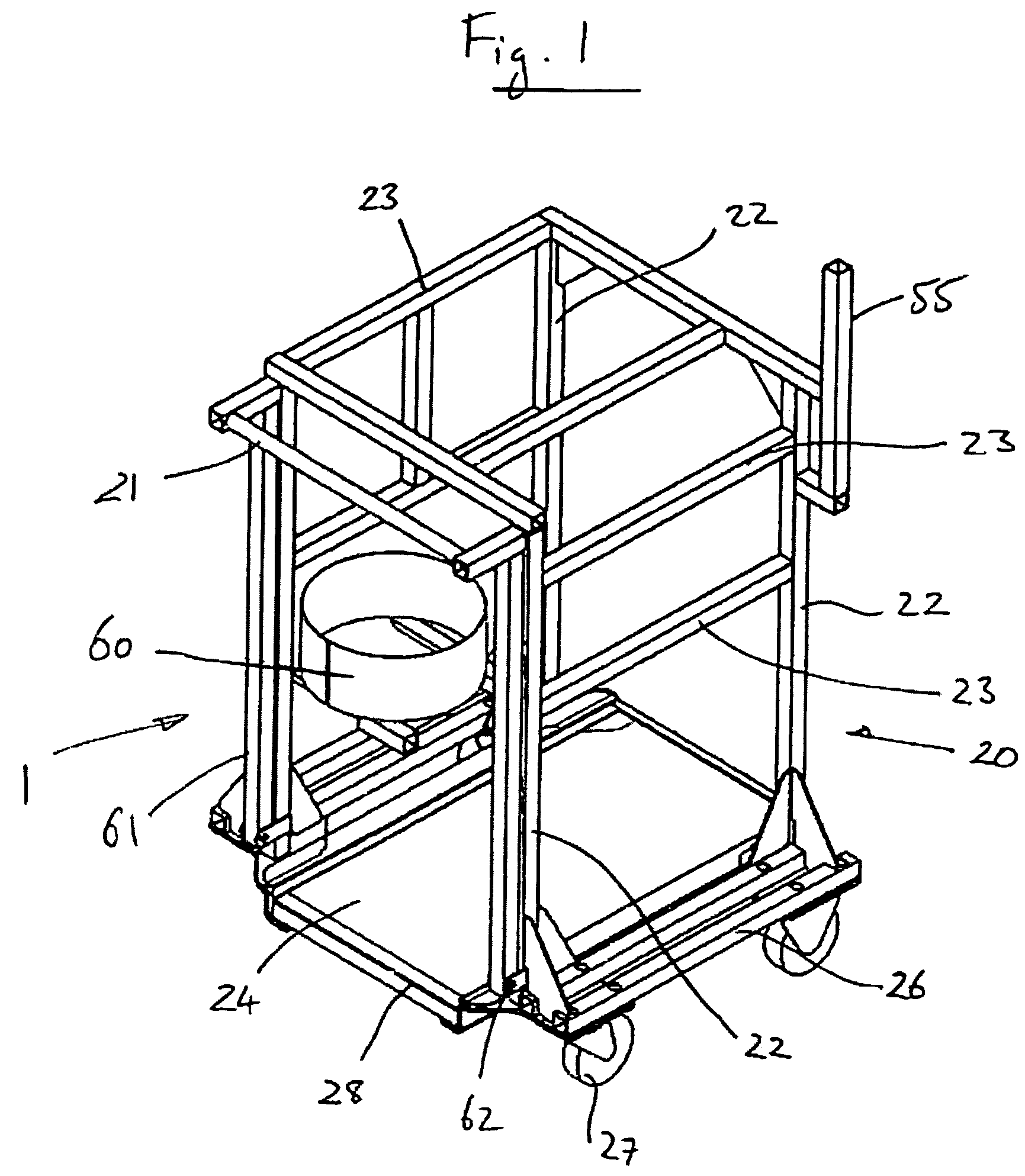
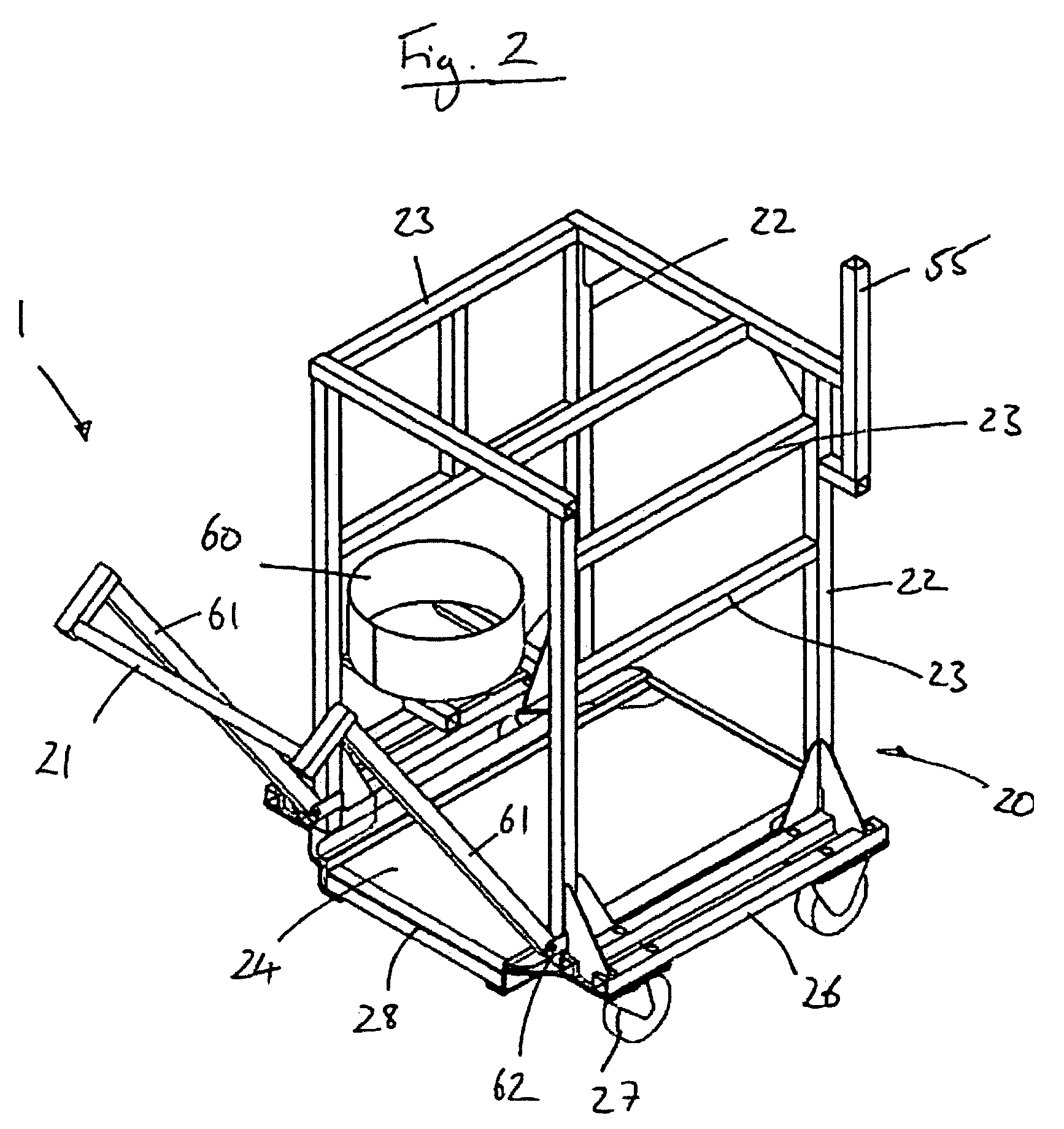
[0037]As shown in FIGS. 7 and 8, the beverage vending machine installation of the present invention generally comprises a trolley unit 1 which is removably installed in a cabinet 12. Referring to FIG. 6, the cabinet 12 comprises a housing 13 with a generally parallelepiped shape having an upper wall 13a, a lower wall 13b, two side walls 13c, a rear panel 13d and two doors 14, 15. The housing 13 is provided with an internal structural framework 18 of metal bars providing structural integrity and cross-bracing to the housing 13. A front face 13e of the housing 13 is open and, in use, is closed by the two doors 14, 15. The two doors 14, 15 form an upper door 14 and a lower door 15. The upper door 14 and lower door 15 are connected by a hinge 60 to the housing 13 and can be moved independently of one another between open and closed positions. Alternatively, the doors 14, 15 may be joined to move effectively as a single door. One or more locks may be provided on both the upper and lower ...


PUM


Abstract

A beverage vending machine installation comprising a cabinet and a trolley unit, the cabinet defining a void in which, in use, the trolley unit can be positioned. The cabinet has an opening and at least one door moveable between open and closed positions. A trolley unit comprises at least one beverage vending machine. The trolley unit is moveable relative to the cabinet between an installed position and an uninstalled position. In the installed position the trolley unit is positioned within the void of the cabinet such that at least one door may be closed to allow operation of the vending machine installation. In the uninstalled position, the trolley unit is removed from the cabinet after opening at least one door to allow access to the trolley unit.

Description

FIELD OF THE INVENTION[0001]The present invention relates to a beverage vending machine installation of the type commonly used, for example, for dispensing coffee and tea beverages.BACKGROUND OF THE INVENTION[0002]Vending machines for dispensing beverages such as coffee are well-known in the art. Typically, such vending machines allow for delivery of beverages in a ‘self-service’ mode of operation where a customer operates the vending machine without direct external supervision. Vending machines of this type may be provided as a stand-alone item situated on a worktop, bench or similar. Alternatively, where the vending machine is to be used in a public place as opposed to a private setting, it is known to locate the vending machine within a cabinet to form a vending machine installation. Typical locations for such vending machine installations include service stations and the communal areas of public buildings such as theatres, gymnasiums, cinemas, etc. The cabinet in which the vendi...

Claims


Application Information

Patent Timeline
IPC IPC(8): B60P3/22G07F9/10G07F11/44G07F13/06
CPCG07F9/10G07F11/44G07F13/065A47J31/00
Inventor SAUNDERS, ANTHONY KEVINROGERS, NEIL MARTINBENTLEY, ANDREW CHARLES
Owner KRAFT FOODS R & D INC
Why Eureka
Try Eureka