

Fluid supply nozzle, substrate processing apparatus and substrate processing method
a technology of supply nozzle and substrate, which is applied in the direction of watering devices, cleaning using liquids, coatings, etc., can solve the problems of long time required to determine the optimum conditions for substrate processing, complicated apparatus structure, and inability to meet the needs of substrate processing, so as to improve the efficiency of substrate processing, reduce the damage to the pattern, and increase the flow rate of fluid
- Summary
- Abstract
- Description
- Claims
- Application Information
AI Technical Summary
Benefits of technology
Problems solved by technology
Method used
Image

Examples
first embodiment
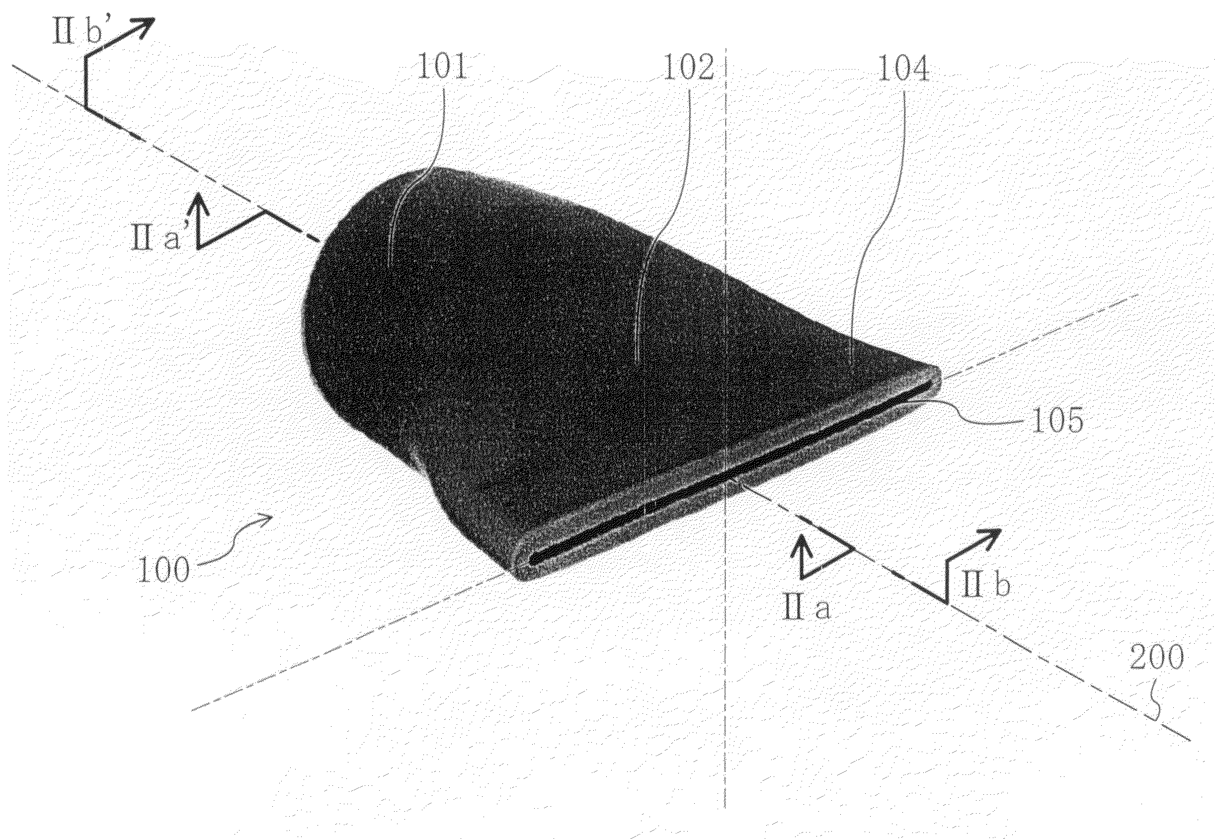
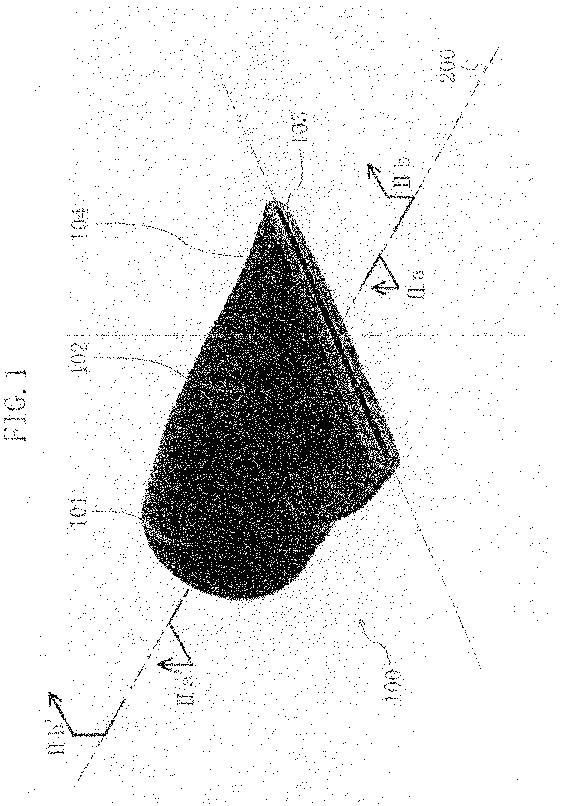
[0073]FIG. 1 is a view illustrating the appearance of a fluid supply nozzle 100 according to a first embodiment of the present invention.
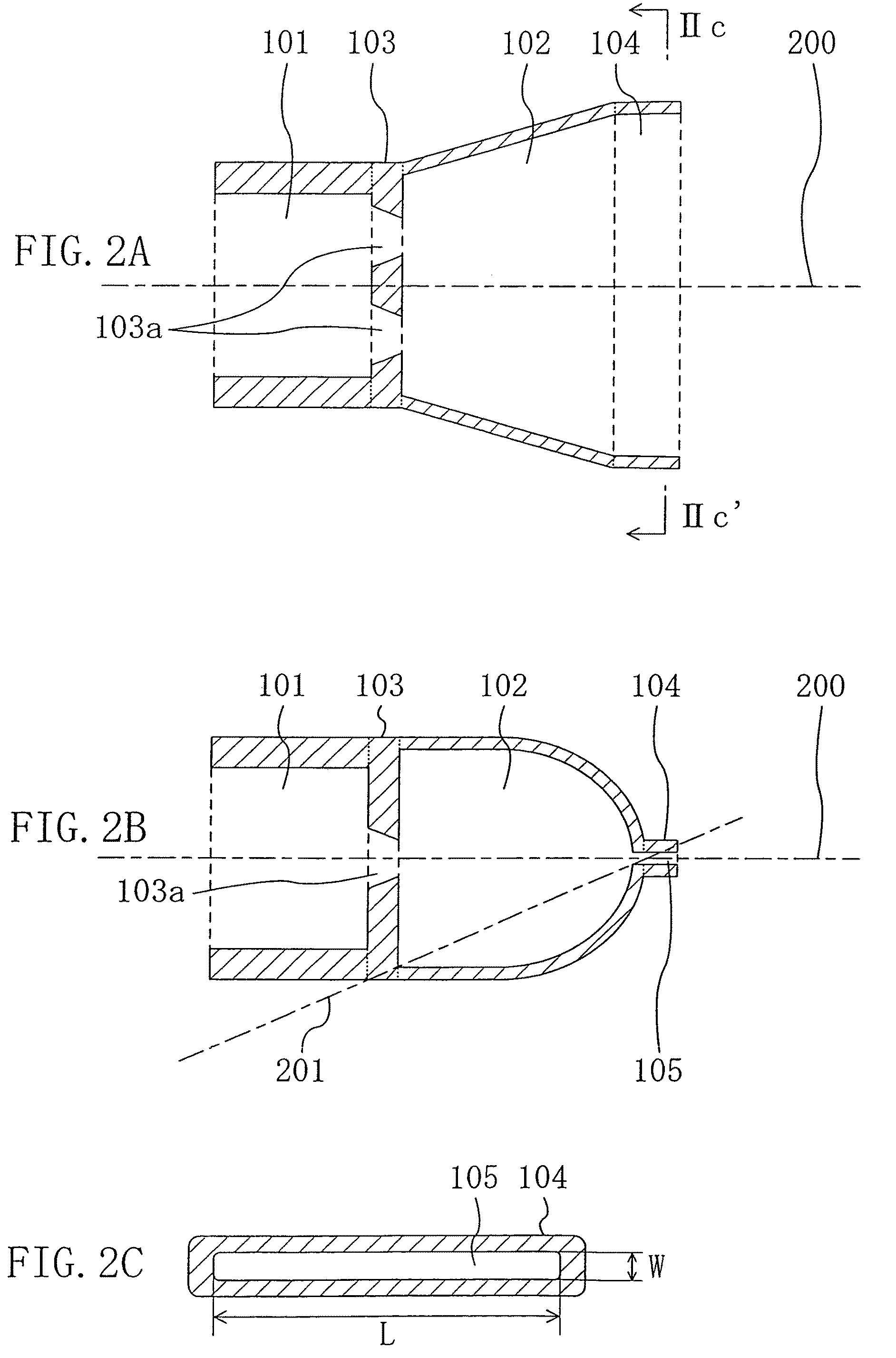
[0074]Moreover, FIG. 2A is a view illustrating a cross section (which will be hereinafter referred to as a “horizontal cross section”) taken along the line IIa-Iia′ of FIG. 1 and FIG. 2B is a view illustrating a cross section (which will be hereinafter referred to as a “vertical cross section”) taken along the line IIb-IIb′ of FIG. 1.
[0075]As shown in FIG. 1 and FIGS. 2A and 2B, a fluid supply nozzle 100 includes a fluid flow-in section 101, a reservoir section 102 for storing a fluid flowing in the fluid flow-in section 101, a flow velocity control wall 103 (not shown in FIG. 1) provided between the fluid flow-in section 101 and the reservoir section 102, and a discharging section 104 connected to the reservoir section 102. The flow velocity control wall 103 has a flat plate shape and includes an orifice 103a for passing a fluid therethrough while...
second embodiment
[0142]Next, a substrate processing apparatus according to a second embodiment of the present invention will be described with reference to the accompanying drawings.
[0143]FIG. 7 is a diagram schematically illustrating the structure of a single-wafer-processing substrate processing apparatus using the fluid supply nozzle 100 of the first embodiment. With the apparatus, as an example, a silicon substrate is processed.
[0144]A rotation table 301 is horizontally disposed in a processing chamber 300. The rotation table 301 is connected to a driving section 302 so as to be rotated by a rotation operation of the driving section 302.
[0145]A silicon substrate 303 is disposed on the rotation table 301 and is rotated with the rotation table 301.
[0146]In the processing chamber 300, a chemical solution supply nozzle 304 for supplying a chemical solution used for performing processing such as etching to the silicon substrate 303 and a pure water supply nozzle 305 for performing pure water cleaning...
third embodiment
[0167]Next, a fluid supply nozzle according to a third embodiment of the present invention will be described with reference to the accompanying drawings.
[0168]FIG. 8 is a view illustrating a vertical cross section of a fluid supply nozzle 150 according to this embodiment. FIG. 8 corresponds to FIG. 2B illustrating a vertical cross section of the fluid supply nozzle 100 of the first embodiment. Except for points made in the following description, an appearance of the fluid supply nozzle 150 is similar to that of the fluid supply nozzle 100 of FIG. 1. Moreover, the fluid supply nozzle 150 has a similar horizontal cross section to that of FIG. 2A. Thus, in FIG. 8, each member also shown in FIG. 2B is identified by the same reference numeral and therefore detail description thereof will be omitted. Each of FIG. 2A and FIG. 8 is a cross-sectional view schematically illustrating the structure of each of the fluid supply nozzles 100 and 150 but different scales are used in FIG. 2A and FIG....
PUM
 Abstract
Description
Claims
Application Information