
Decanter type centrifugal separator with torque transmission mechanism

a centrifugal separator and torque transmission technology, which is applied in the direction of centrifuges, rotary centrifuges, etc., can solve the problems of damage to the internal gear, and insufficient torsional vibration absorption at each transmission part, so as to increase the damping of self-excited vibration, high viscosity, and high viscosity

Active Publication Date: 2010-03-02
TOMOE ENGINEERING CO LTD
View PDF12 Cites 3 Cited by
  • Summary
  • Abstract
  • Description
  • Claims
  • Application Information

AI Technical Summary

Benefits of technology

This solution effectively absorbs torsional vibrations, reducing the required capacity of the differential gear unit and allowing the decanter type centrifugal separator to operate at approximately 2 to 3 times its conventional treatment capacity without torque fluctuations.

Problems solved by technology

As a result, there may be problems including damage of an internal gear due to an impact load (torque) being imposed on a differential gear unit 150, and a crack in a stock solution feed hole part 144 at 45 degrees due to a torsion of a screw conveyor cylindrical hub 141 (boss).
As a result, it is difficult to absorb the torsional vibrations generated in the conveyor at each transmission part.
Accordingly, it is insufficient for absorbing the torsional vibration.

Method used


Image

  • Decanter type centrifugal separator with torque transmission mechanism
  • Decanter type centrifugal separator with torque transmission mechanism
  • Decanter type centrifugal separator with torque transmission mechanism

Examples


first embodiment

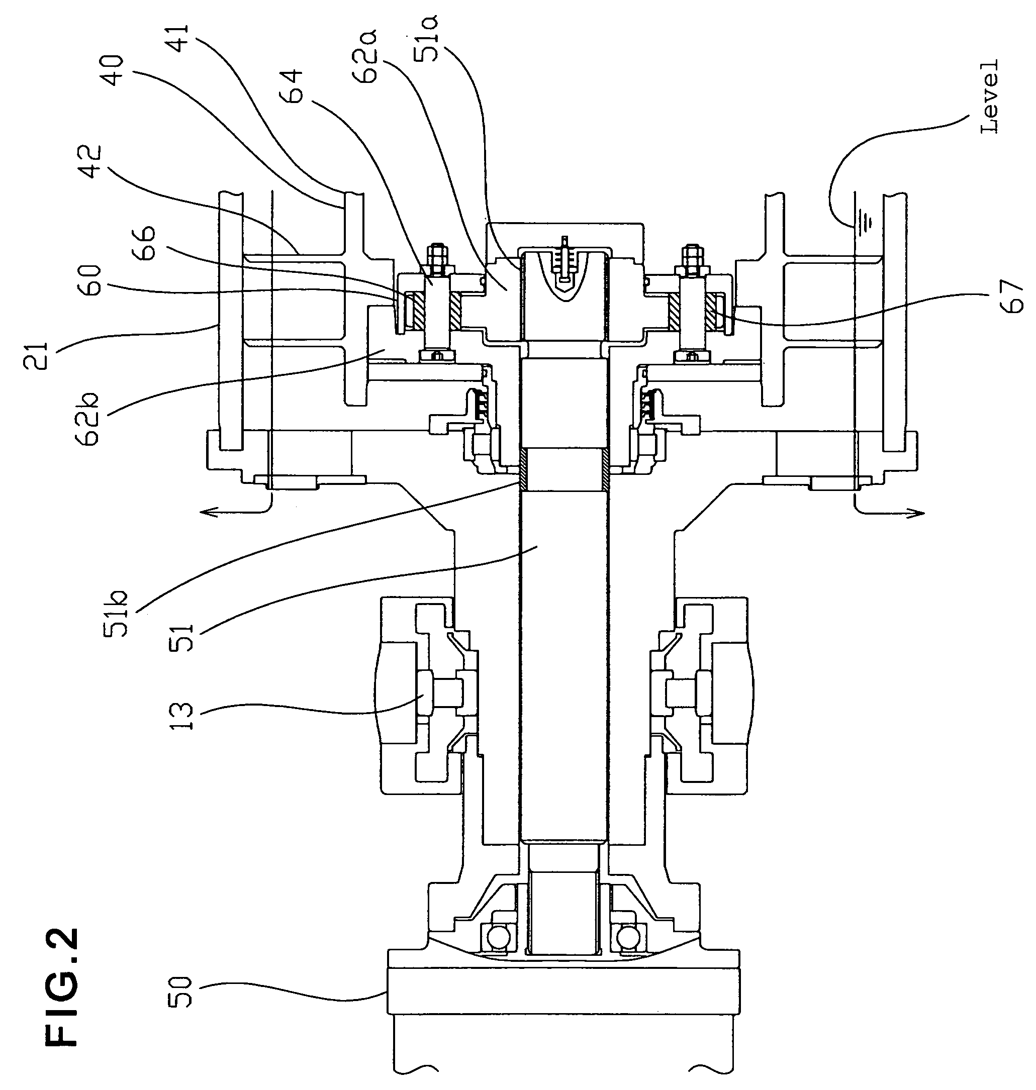
[0026]FIG. 1 and FIG. 2 show the present invention.

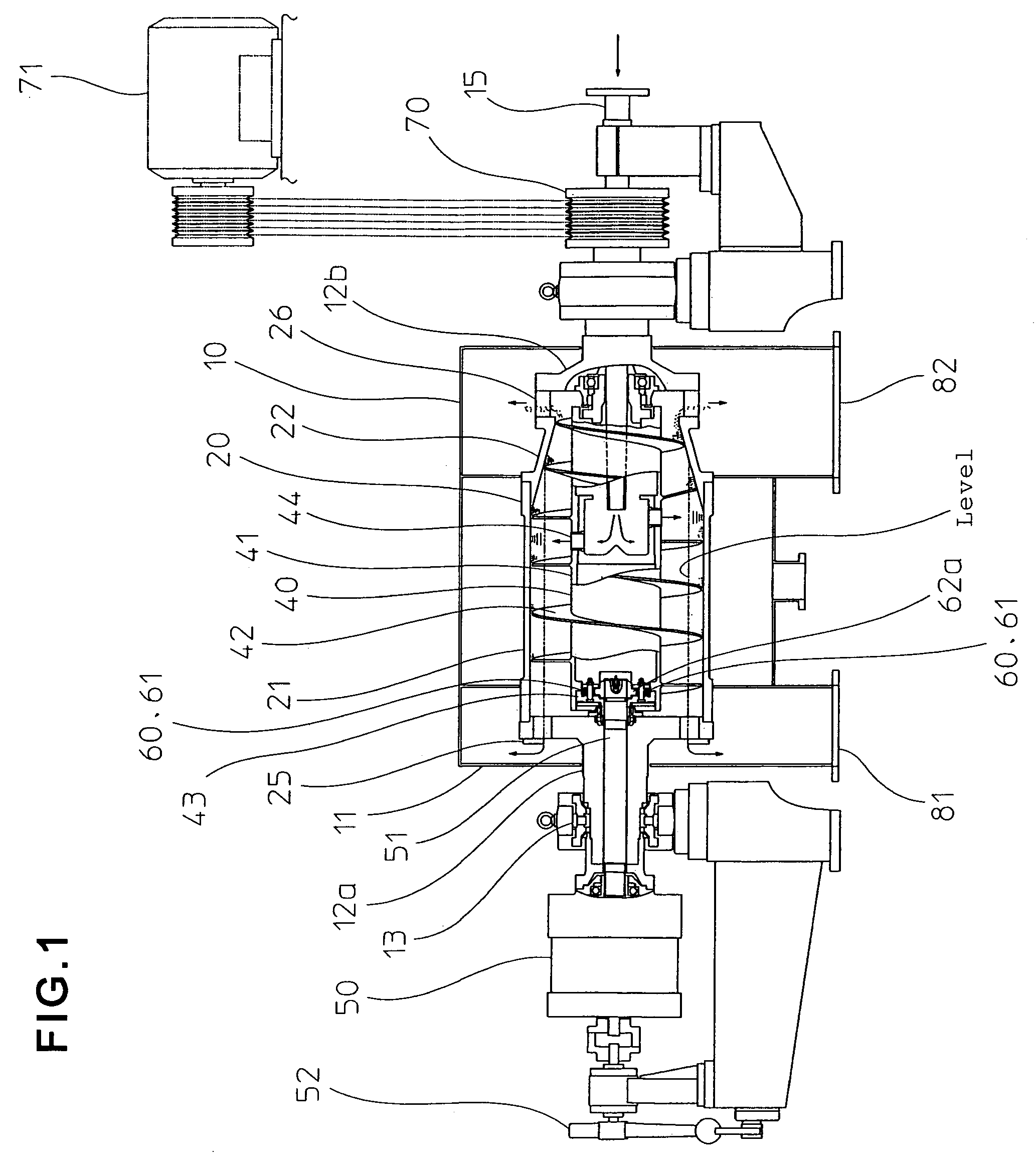
[0027]A decanter type centrifugal separator 10 comprises a bowl 20 having a cylindrical part 21, a conical part 22, a separated liquid discharge dam part 25, and a dewatered solid discharge port 26; a screw conveyor 40 for axially conveying sedimentation solid that is inserted into the bowl 20, and is arranged so that it is coaxial with the bowl 20, and can be rotated at a speed different from that of the bowl 20, as well as processed liquid feed means 15; a separated liquid discharge port 81; a solid discharge port 82; drive means 71; and a differential gear unit 50 which produces a difference in speed between the bowl 20 and the screw conveyor 40.

[0028]The bowl 20 of the decanter type centrifugal separator 10 has an inside diameter of 740 mm, and the bowl 20 is rotated at a speed of 1700 to 2800 min−1 for a centrifugal force of 1200 G to 3200 G, while an internal screw conveyor flight 42 is rotated at a speed of 1620 to 2760 min−1...

second embodiment

[0035]FIG. 3 shows the present invention.

[0036]The same components as those in the first embodiment will be provided with the same reference numerals.

[0037]The bowl 20 of the decanter type centrifugal separator 10 pertaining to the present embodiment also has an inside diameter of 740 mm, and the bowl 20 is rotated at a speed of 1700 to 2800 min−1 for a centrifugal force of 1200 G to 3200 G, while an internal screw conveyor flight 42 is rotated at a speed of 1620 to 2760 min−1 in the same direction as the bowl 20, slower than the bowl 20 by a difference in speed of 40 to 80 min−1 or so, whereby the solid precipitated in the liquid inside the bowl 20 can be axially conveyed. The solid is further drawn up from the liquid by the screw conveyor flight 42 in the conical part 22, whereby it is dehydrated in the course of being axially conveyed, and is continuously discharged to the outside of the decanter type centrifugal separator 10 through the solid discharge port 82.

[0038]On the other...

third embodiment

[0044]FIG. 8 and FIG. 9 show the present invention.

[0045]The same components as those in the first embodiment will be provided with the same reference numerals.

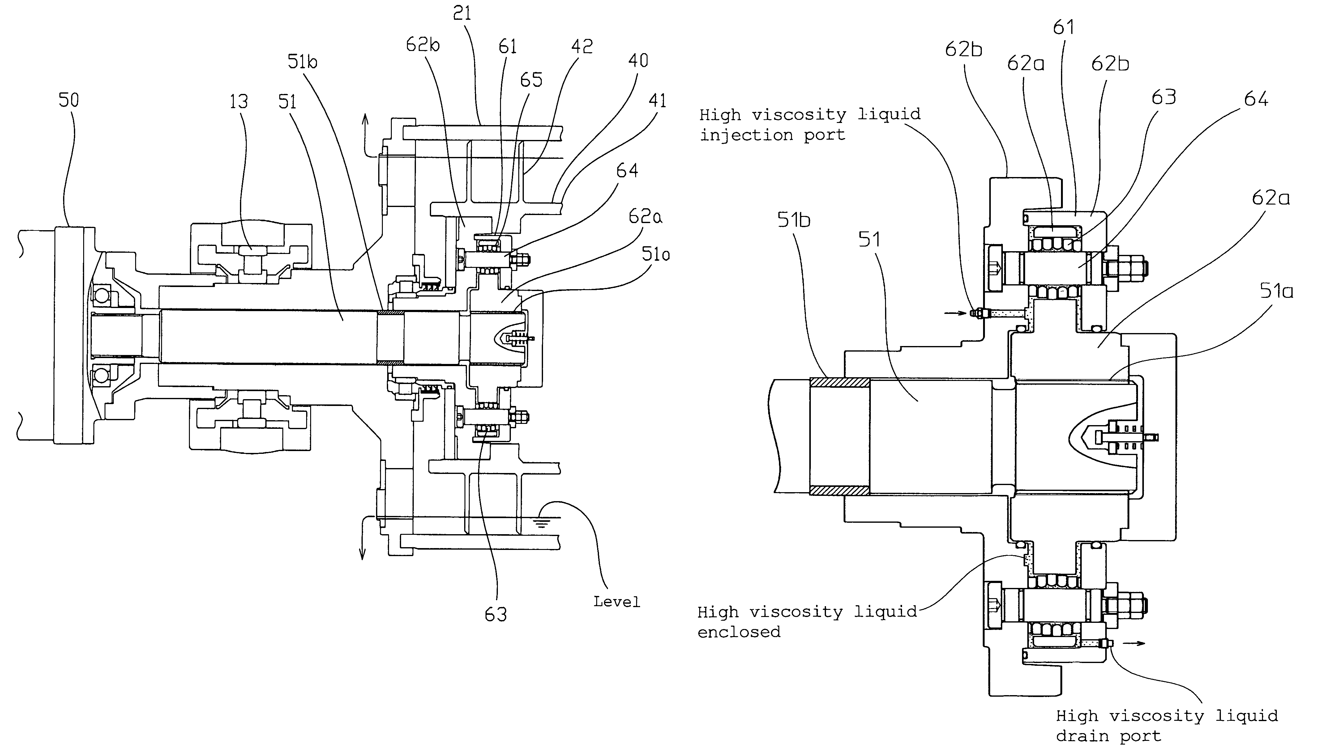
[0046]In the decanter type centrifugal separator 10 pertaining to the present embodiment, the entire assembly inside the torque transmission mechanism 60, 61 as given in the first embodiment or second embodiment that is included in the joint part 43 on the side of the screw conveyor 40 of the drive transmission shaft 51 between the differential gear unit 50 and the screw conveyor 40 is immersed in a high viscosity liquid, such as silicone oil, or the like, or a high viscosity substance, such as silicone rubber (initially liquid, but vulcanized into a gummy state as time elapses), or the like, as a measure against torsional self-excited vibration of the screw conveyor 40 that can occur between the bowl 20 and the tip of the screw conveyor flight 42 through the treatment substances, such as PVC crystalline particles, or the lik...


PUM


Abstract

A decanter type centrifugal separator includes a torque transmission mechanism with enhanced effect of absorbing a torsional vibration. The decanter type centrifugal separator (10) includes a bowl (20); a screw conveyor (40) disposed in the bowl (20); a processed liquid feed portion (15); a separated liquid discharge port (81); a solid discharge port (82); a drive portion (71); and a differential gear unit (50) for generating a difference in speeds between the bowl (20) and the screw conveyor (40). A torque transmission mechanism (60, 61) includes an elastic damping member (67) for absorbing the torsional vibration of the screw conveyor (40).

Description

TECHNICAL FIELD[0001]The present invention relates to a decanter type centrifugal separator for use in separation and dehydration treatment of crystalline particles, such as those of PVC (polyvinyl chloride), terephthalic acid, and the like, in the chemical industry, and in separation and dehydration treatment of starch ground milk, and the like, in the food industry.BACKGROUND ART[0002]In a conventional decanter type centrifugal separator 100 shown in FIG. 10, during separation and dehydration treatment of crystalline particles, such as those of PVC (polyvinyl chloride), terephthalic acid, or the like, or starch ground milk, or the like, when a throughput thereof increases during the conveyance and dehydration treatment of centrifugally precipitated particles (solid) along an axial direction thereof through a minute difference in speeds between a bowl 120 and a screw conveyor 140 disposed therein, chattering (torsional self-excited vibration) of the screw conveyor 140 is generated ...

Claims


Application Information

Patent Timeline
Patent Type & Authority Patents(United States)
IPC IPC(8): B04B1/20B04B9/14
CPCB04B1/2016B04B9/12
Inventor FUJIMOTO, KOJIOHASHI, JUN
Owner TOMOE ENGINEERING CO LTD
Learn More