Catadioptric imaging system exhibiting enhanced deep ultraviolet spectral bandwidth

a technology of deep ultraviolet spectral bandwidth and catadioptric optical system, which is applied in the field of optical imaging, can solve the problems of increasing the difficulty of chromatic correction in the duv region, and achieve the effect of high spectral bandwidth

Inactive Publication Date: 2010-03-02
KLA CORP
View PDF59 Cites 3 Cited by
  • Summary
  • Abstract
  • Description
  • Claims
  • Application Information

AI Technical Summary

Problems solved by technology

Chromatic correction becomes increasingly difficult for performance in the DUV region.
Previous designs do not demonstrate this capability

Method used


Image

  • Catadioptric imaging system exhibiting enhanced deep ultraviolet spectral bandwidth
  • Catadioptric imaging system exhibiting enhanced deep ultraviolet spectral bandwidth
  • Catadioptric imaging system exhibiting enhanced deep ultraviolet spectral bandwidth

Examples


Embodiment Construction

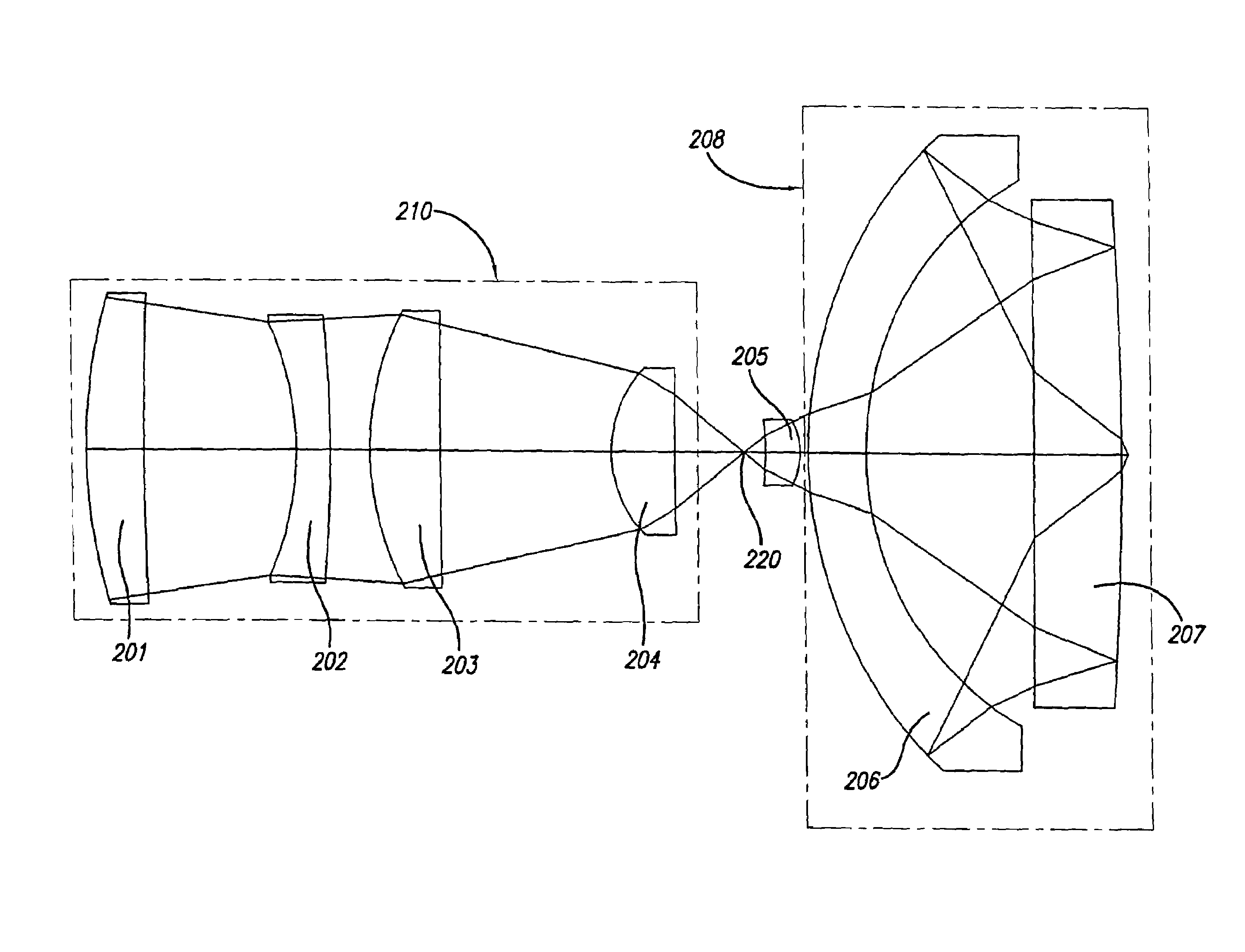
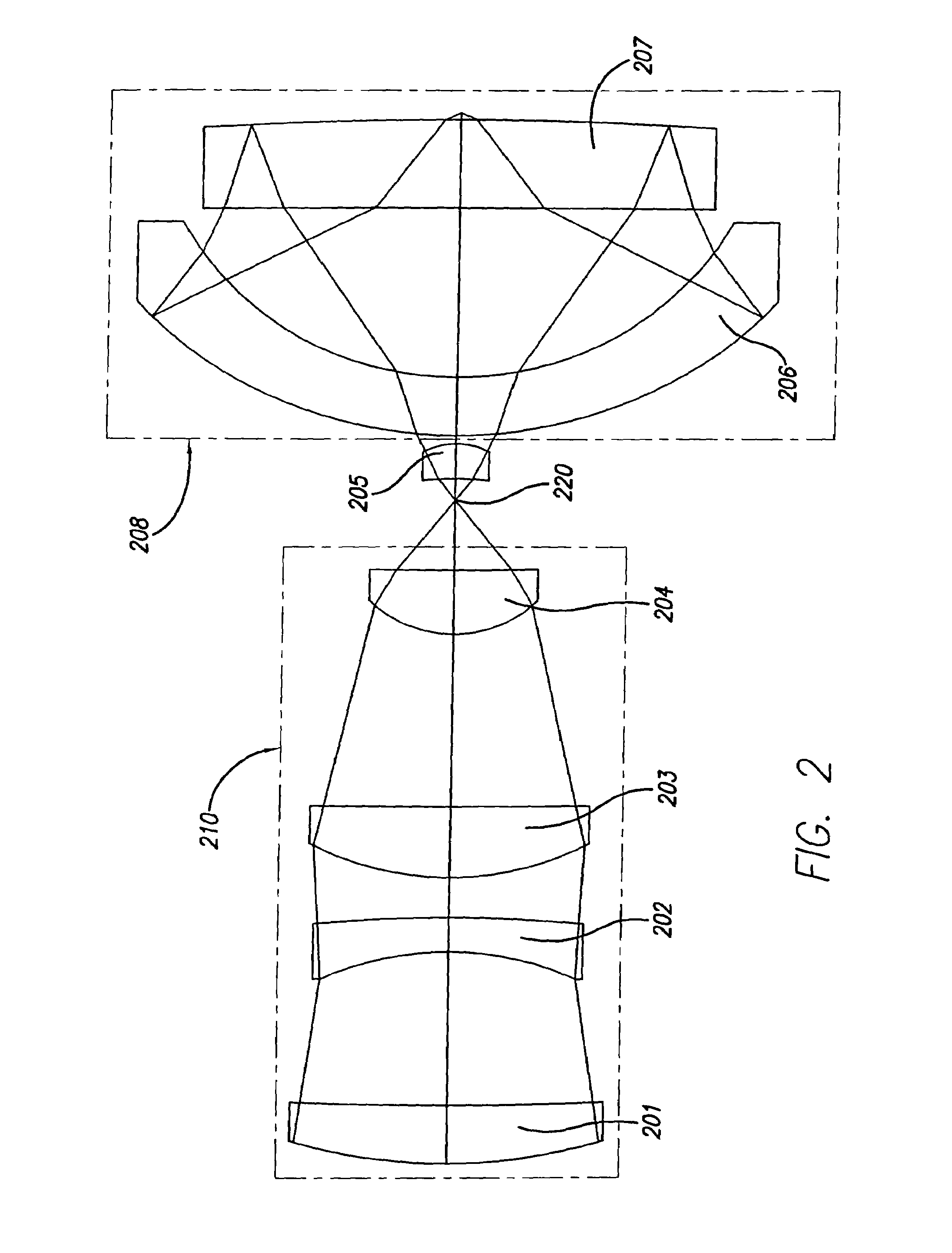
[0018]According to the present invention, there is provided a catadioptric objective having improved spectral bandwidth in advanced applications, such as microscopy and semiconductor wafer inspection. In general, the design may comprise lenses formed from a single glass or using a single glass with a field lens or lenses and possibly a front or first lens constructed from another glass, where the field lens or lenses may generally be disposed toward a mangin mirror / lens or catadioptric group and away from an intermediate image point.

[0019]Established Designs

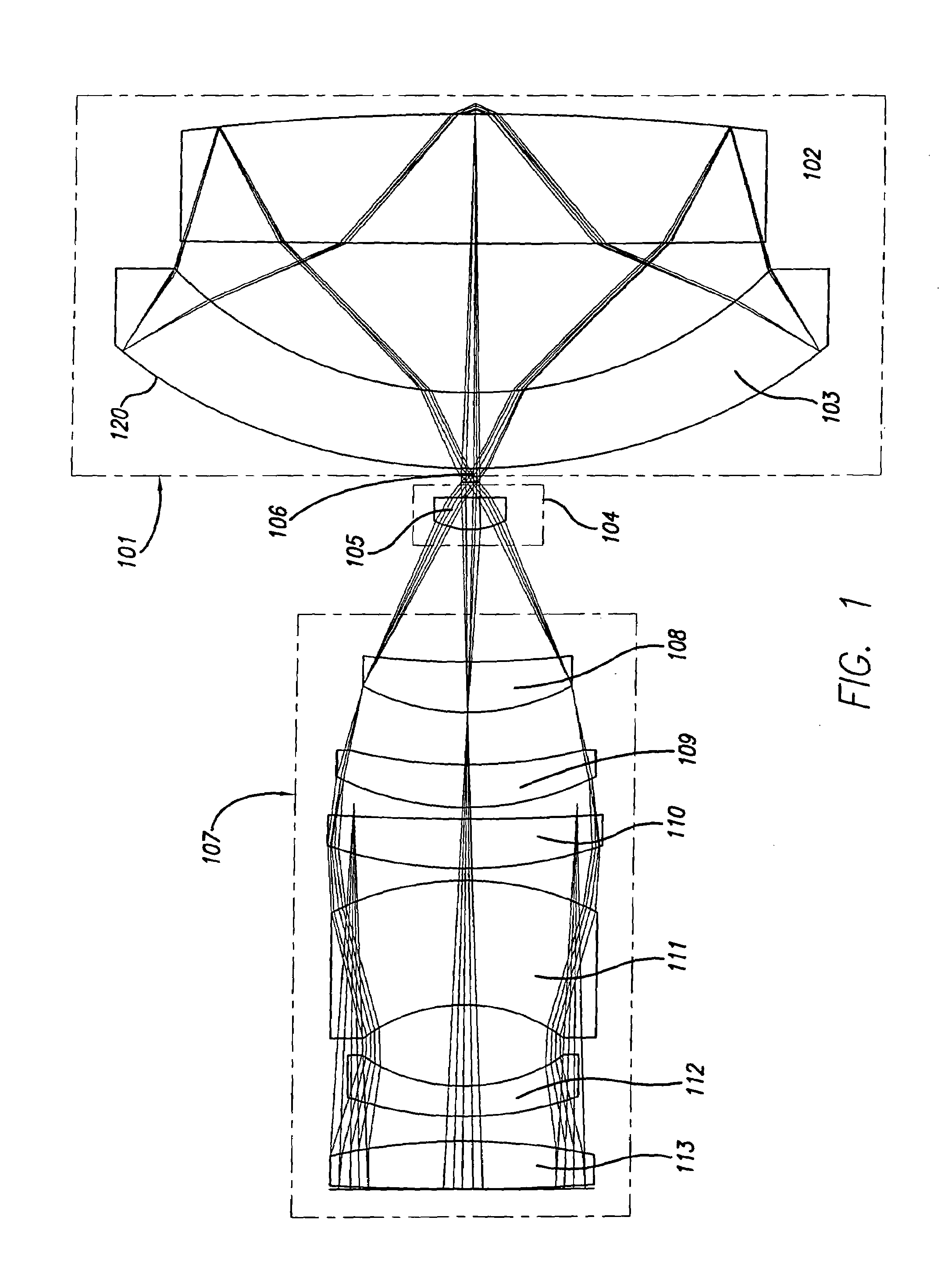
[0020]One previous objective design is shown in FIG. 1. The catadioptric objective as shown in FIG. 1 is optimized for broad-band imaging in the UV spectral region, namely approximately 0.285 to 0.320 micron wavelengths. The objective provides relatively high numerical apertures and large object fields. The design of FIG. 1 uses the Schupmann principle in combination with an Offner field lens to correct for axial color and first ...


PUM

PropertyMeasurementUnit
wavelengthsaaaaaaaaaa

Abstract

A relatively high spectral bandwidth objective employed for use in imaging a specimen and method for imaging a specimen is provided. The objective includes a lens group having at least one focusing lens configured to receive light energy and form an intermediate image, at least one field lens oriented to receive the intermediate image and provide intermediate light energy, and a Mangin mirror arrangement positioned to receive the intermediate light energy and apply light energy to the specimen. The objective may provide, in certain instances, a spectral bandwidth up to approximately 193 to 266 nanometers and can provide numerical apertures in excess of 0.9. Elements are less than 100 millimeters in diameter and may fit within a standard microscope. The field lens may include more than one lens and may be formed of a material different from at least one other lens in the objective.

Description

[0001]This application is a continuation-in-part of U.S. patent application Ser. No. 10 / 434,374, entitled “High Performance Catadioptric Imaging System,” inventors David G. Shafer, et al., filed May 7, 2003, which claims the benefit of U.S. Provisional Patent Application Ser. No. 60 / 449,326, entitled “High Performance, Low Cost Catadioptric Imaging System,” filed Feb. 21, 2003.BACKGROUND OF THE INVENTION[0002]1. Field of the Invention[0003]The present invention relates generally to the field of optical imaging and more particularly to catadioptric optical systems used for microscopic imaging, inspection, and lithography applications.[0004]2. Description of the Related Art[0005]Many optical systems have the ability to inspect or image features on the surface of a specimen, such as inspecting defects on a semiconductor wafer or photomask, or alternately examining a biological specimen on a slide. Microscopes have been used in various imaging situations, including biology, metrology, s...

Claims


Application Information

Patent Timeline
Patent Type & Authority Patents(United States)
IPC IPC(8): G02B5/08G02B17/08G02B21/02G03F7/20
CPCG02B17/0808G02B17/0812G02B17/0856G03F7/70341G02B21/02G03F7/70225G02B17/0892
Inventor ARMSTRONG, J. JOSEPHCHUANG, YUNG-HOSHAFER, DAVID R.
Owner KLA CORP
Why Eureka
Try Eureka