
Method for shallow water flow detection

a technology of shallow water flow and detection method, which is applied in the direction of instruments, analogue processes for specific applications, electric/magnetic computing, etc., can solve the problems of swf layers costing the oil industry hundreds of millions of dollars to date, and can be expensive and risky for drilling for fossil fuels in deepwater targets

Active Publication Date: 2010-03-02
WESTERNGECO LLC
View PDF2 Cites 44 Cited by
  • Summary
  • Abstract
  • Description
  • Claims
  • Application Information

AI Technical Summary

Benefits of technology

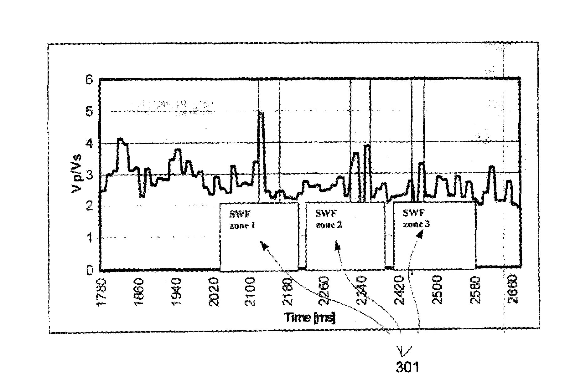
[0018]The disclosed method may have one or more of the following advantages. The method can be trendline independent using a deepwater rock model for geopressure analysis. It can be based on several seismic attributes, such as velocities and amplitudes and can be calibrated with offset well information. Pore pressure can be calculated as the difference between overburden stress and effective stress. The effective stress can affect the grain-to-grain contacts of elastic, sedimentary rock, and consequently, the velocities of seismic waves propogating through such rocks.

Problems solved by technology

Drilling for fossil fuels in deepwater targets can be expensive and risky if not well planned and prepared.
If a deep-sea drill permeates these SWF layers, the sands can flow and cause extensive damage to the borehole and the well site.
SWF layers have cost the oil industry hundreds of millions of dollars to date.
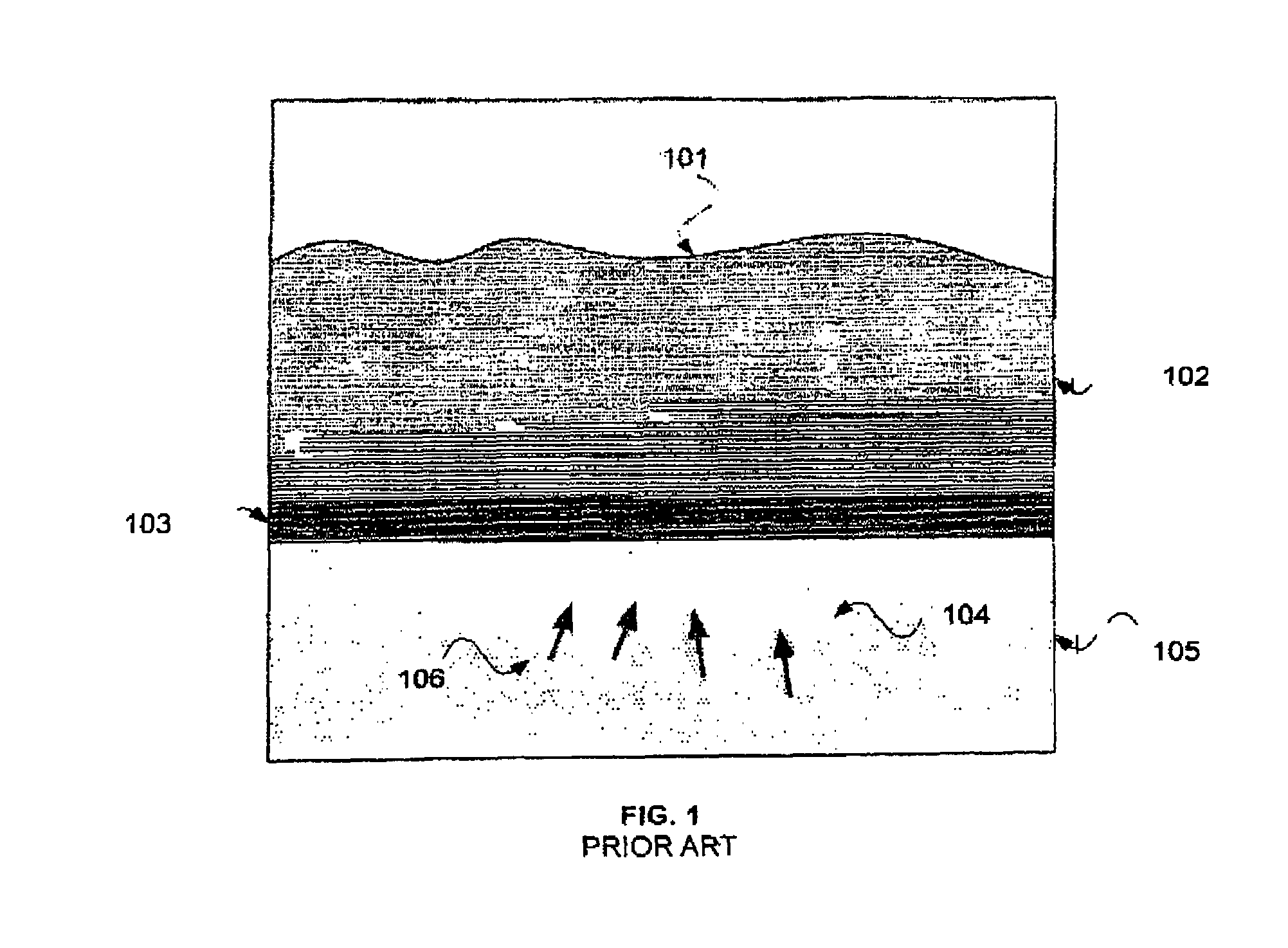
When a drill bit punctures the SWF layer, the resulting over-pressured sand 104 can flow at the wellhead and pose drilling, environmental, and health problems.
For example, SWF can cause drilling template-blowouts, buckling of casing, loss of well or wellhead, costly downtime in rig, and can result in leakage of hydrocarbon in the seabed, which can cause severe environmental damage.
There are several problems with the conventional approach.
First, conventional seismic stacking velocities are usually unsuited for pressure prediction because they are not rock or propagation velocities.
Second, these velocities lack resolution in depth.
Third, in a deepwater environment, sediment loading often has been so fast that fluid pressures in these sediments are above hydrostatic below the mud line.
This prevents development of a normal compaction trend; thus invalidating the entire approach in deepwater.

Method used


Image

  • Method for shallow water flow detection
  • Method for shallow water flow detection
  • Method for shallow water flow detection

Examples


Embodiment Construction

[0030]Surface seismic data are useful in predicting SWF zones because they are available before drilling begins in the deepwater wells.

Processing of High-Resolution 3D Seismic Data

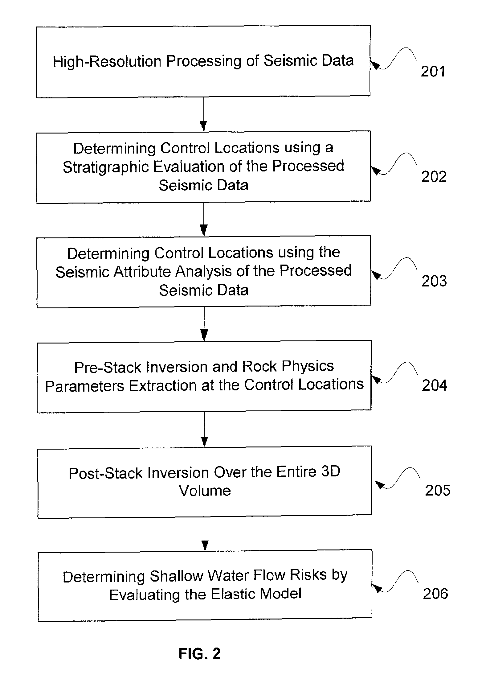
[0031]FIG. 2 shows a flowchart for the detection of SWF. First, seismic data can be processed to enhance its stratigraphic resolution 201. The stratigraphic resolution is the ability to differentiate and resolve stratigraphic features in a seismic image. The enhanced resolution improves the frequency content of the seismic data and can be used more effectively to detect thin sand bodies.

[0032]The seismic data that is used can either be acquired solely for detection of SWF, or can be seismic data that has been acquired for different modeling purposes, and reprocessed for detection of SWF. The seismic data can be three-dimensional (“3D”), two-dimensional (“2D”), or one-dimensional (“1D”) data. For example, borehole 1D data can be used to detect SWF, and full 3D seismic data can be used to detect SWF in a wel...


PUM


Abstract

The present invention presents a method for determining shallow water flow risk using seismic data. The seismic data can be processed to enhance its stratigraphic resolution by sub-sampling the seismic data to less than a two-millisecond interval. Performing a stratigraphic analysis on the seismic data and evaluating the seismic attributes of the seismic data can be used to select a control location. A pre-stack waveform inversion is applied to seismic data at a selected control location to provide an elastic model, which includes pressure-wave velocity and shear-wave velocity. The shallow water flow risk is then determined using the elastic model by comparing the pressure-wave velocity to the shear-wave velocity. A post-stack inversion can be applied on the seismic data using the elastic model to model a 3D volume to determine the shallow water flow risk across the 3D volume.

Description

FIELD OF INVENTION[0001]This invention relates to the prediction of shallow water flow sands using processed seismic data.BACKGROUND[0002]Drilling for fossil fuels in deepwater targets can be expensive and risky if not well planned and prepared. Proper well planning requires reliable anticipation of geohazards. One such geohazard in deepwater drilling is shallow water flow (“SWF”) sands, which are highly porous sands that are prone to flowing when drilled. If a deep-sea drill permeates these SWF layers, the sands can flow and cause extensive damage to the borehole and the well site. SWF layers have cost the oil industry hundreds of millions of dollars to date. Detection of the SWF layers, therefore, is important for reducing both commercial loses and environmental risks.[0003]FIG. 1 is a representation of the current understanding of the formation of a SWF. SWF sands can occur in water depths between 300 m and 600 m below the mud line 101. They are found all over the world in areas ...

Claims


Application Information

Patent Timeline
IPC IPC(8): G06G7/48G06G7/50G01V1/00G01V1/28G01V1/32G01V9/02
CPCG01V1/282G01V1/288G01V1/32G01V9/02Y02A90/30
Inventor DUTTA, NADERMALLICK, SUBHASHIS
Owner WESTERNGECO LLC
Learn More