Transmitter and control method for same

a control method and transmitter technology, applied in the direction of pulse generator, pulse technique, electronic switching, etc., can solve the problems of substantially affecting the reception and data signals of the receiver, and the idle state of the receiver as data, so as to improve the reliability of data signals and suppress the noise of data signals arising from the charge storage effect and external noise intrusion

Active Publication Date: 2010-03-09
RENESAS ELECTRONICS CORP
View PDF8 Cites 8 Cited by
  • Summary
  • Abstract
  • Description
  • Claims
  • Application Information

AI Technical Summary

Benefits of technology

[0021]This transmitter of this invention can pass a reverse current, occurring due to the charge storage effect and to external noise intermixing, equally through the first driving current and the second driving current, by inducing an equal current-passing state prior to inducing a non-conducting state in a reverse-current prevention element (for example, a diode). By this means, even when a load resistance is connected between the outputs of the first and second driving circuits, no current flows in the load resistance, and there is no change in the potential difference of the output signals of the first and second driving circuits. Hence data signals are not affected by external noise. That is, by a transmitter of this invention, the imperviousness of data signals to external noise can be enhanced.
[0024]By a transmitter and a transmitter control method of this invention, noise in data signals arising from the charge storage effect and from external noise intrusion can be suppressed, and data signal reliability can be improved.

Problems solved by technology

It is widely known that in an automobile in which a CAN is installed, transmitted and received data signals are substantially affected by external noise.
However, in a FlexRay system, Idle is an intermediate voltage, and thresholds higher and lower than this are provided, with Data1 at or above the higher threshold and Data0 at or below the lower threshold, so that when the Idle signal level exceeds a threshold due to this noise, there is the problem that the receiver may erroneously recognize the Idle state as Data1 or as Data0.

Method used


Image

  • Transmitter and control method for same
  • Transmitter and control method for same
  • Transmitter and control method for same

Examples


fist embodiment

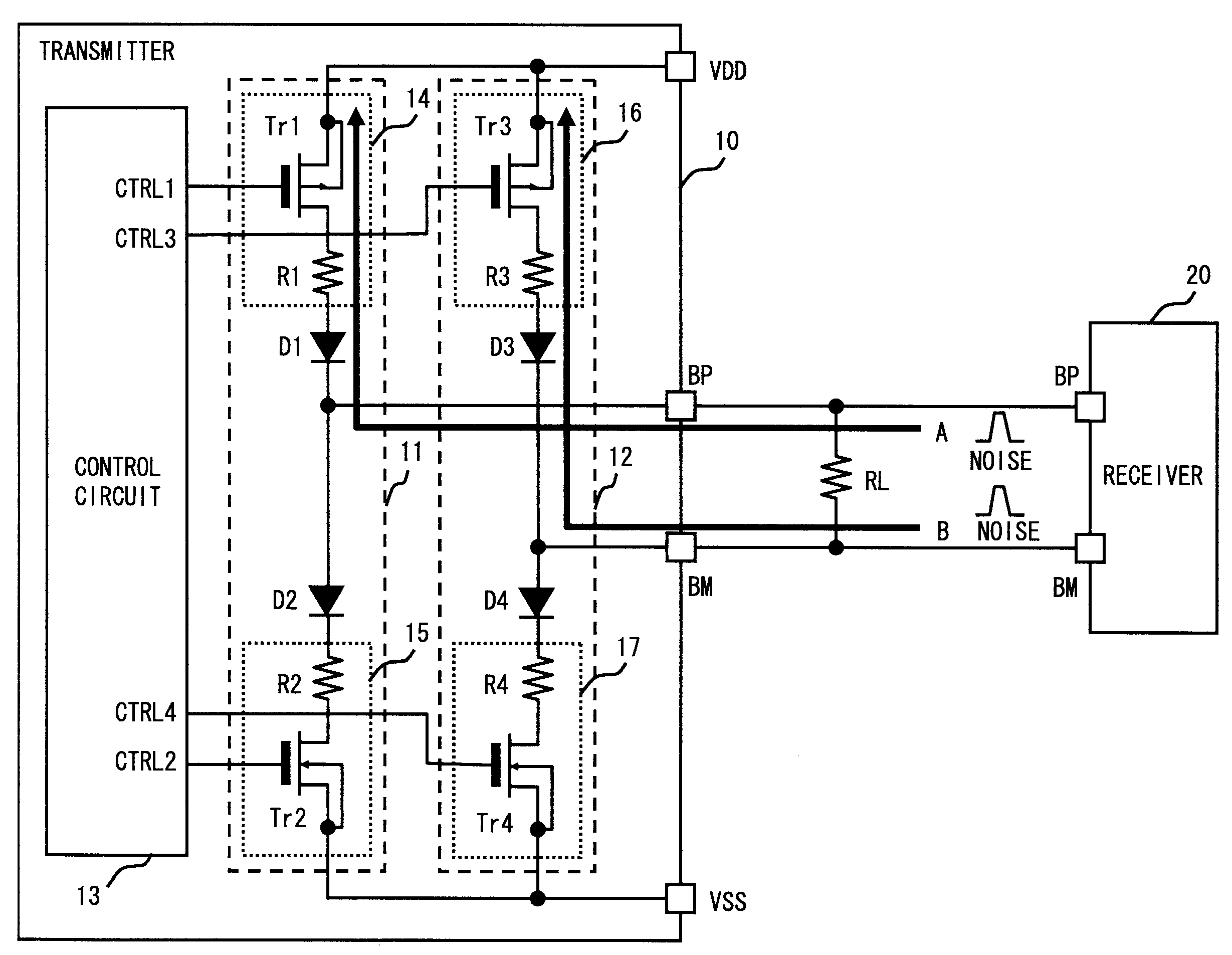
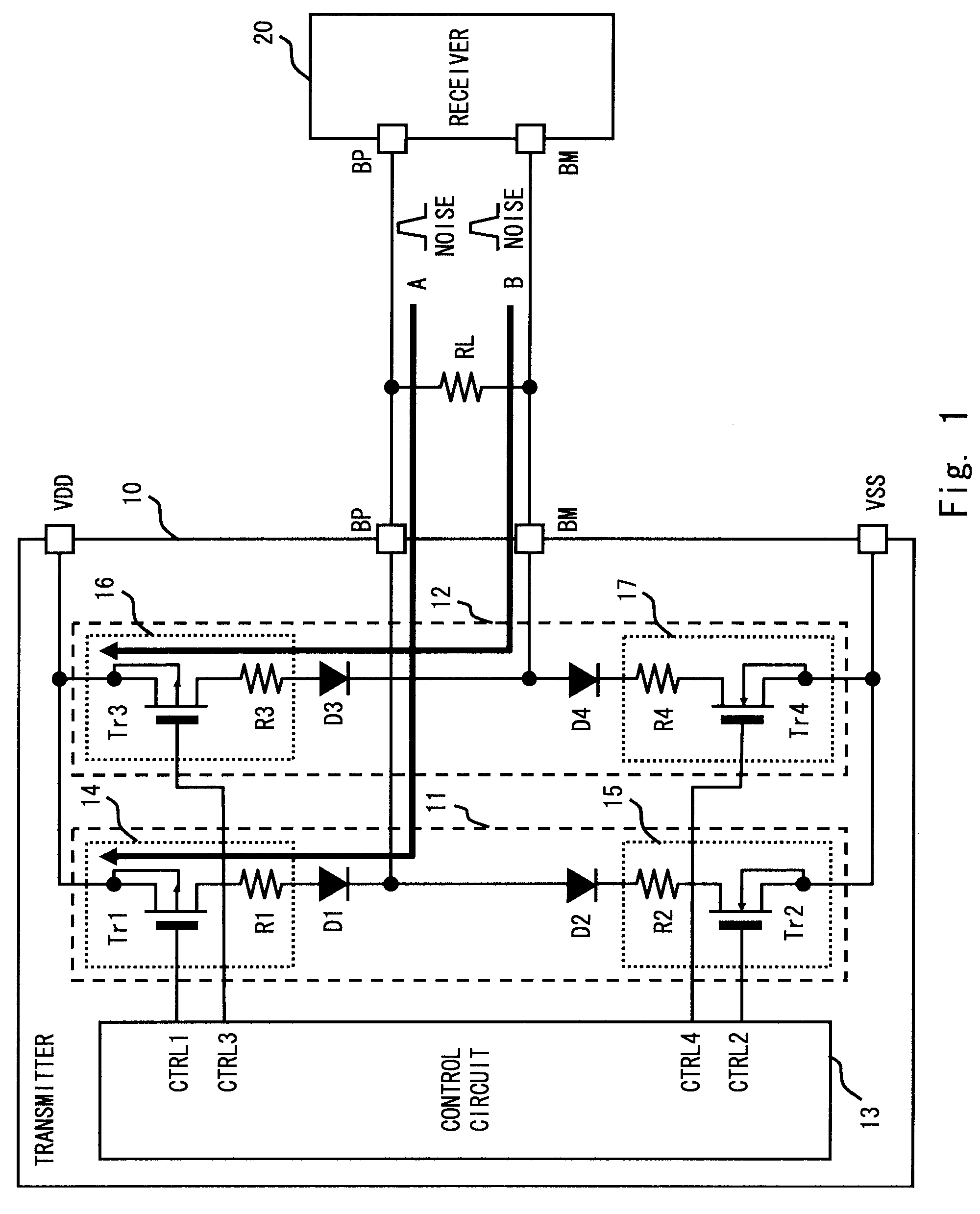
[0038]Below, embodiments of the invention are explained referring to the drawings. The transmitter of a first embodiment is a circuit which performs transmission and reception using three-valued data signals, such as in circuits which perform communications based for example on the FlexRay standard. FIG. 1 shows a circuit diagram of a transmitter 10 according to the first embodiment. In FIG. 1, a receiver 20 which receives signals output by the transmitter 10, and a load resistance RL connecting a pair of data lines, are shown. The transmitter 10 generates a potential difference across the load resistance RL, and the receiver 20 receives data based on this potential difference.

[0039]The transmitter 10 has a power supply terminal VDD, ground terminal VSS, and first and second output terminals (for example, output terminals BP and BM). The receiver 20 has input terminals BP, BM corresponding to the output terminals BP, BM of the transmitter 10. In the following explanation, the line c...

second embodiment

[0061]A circuit diagram of the transmitter 30 of a second embodiment appears in FIG. 3. The current setting circuits 14 to 17 in the transmitter 10 of the first embodiment set, by means of the resistances R1 to R4, the current flowing in the load resistance RL, the voltages at the output terminals BP and BM, and the through currents when all the transistors Tr1 to Tr4 were in the conducting state. On the other hand, the current setting circuits 34 to 37 in the transmitter 30 of the second embodiment use the transistor sizes of the transistors Tr1 to Tr4 to set the current flowing in the load resistance RL and the voltages at the output terminals BP and BM, and use the transistor sizes of transistors Tr1a to Tr4a to set the through currents. Portions which are common to the first embodiment and to the second embodiment are assigned the same symbols, and explanations are omitted.

[0062]The transmitter 30 has first and second driving circuits (for example, driving circuits 31, 32) and a...


PUM


Abstract

A transmitter of the invention, according to a first aspect, has first and second driving circuits with reverse-current prevention elements connected between output terminals and power supply terminals, and a control circuit which controls the outputs of the first and second driving circuits, the control circuit controlling the first and second driving circuits, during a transition from a first state in which the first and second driving circuits output a first or a second logic level to a second state in which the first and second driving circuits output an intermediate level between the first and second logic levels, to induce a third state in which a through current flows in the first and second driving circuits via the reverse-current prevention elements.

Description

BACKGROUND OF THE INVENTION[0001]1. Field of the Invention[0002]This invention relates to a transmitter and to a control method for a transmitter, and in particular relates to a transmitter having a bus driving circuit which outputs differential signals, and to a control method for such a circuit.[0003]2. Description of Related Art[0004]In automotive control technology in recent years, numerous CAN (Controller Area Networks) have been used as networks connecting the various portions of automobiles. A CAN performs data communication using differential signals on a pair of signal lines. A CAN conforms to serial bus communication standards, and signals output to signal lines are generated by transceivers. One example of such a transmitter is disclosed in National Publication of Translated Version No. 2002-509682.[0005]Here, a circuit diagram for a general transmitter 101 used in a CAN appears in FIG. 9. As shown in FIG. 9, the transmitter 101 has a PMOS transistor Tr1 (below simply cal...

Claims


Application Information

Patent Timeline
Patent Type & Authority Patents(United States)
IPC IPC(8): H03K3/00
CPCH03F1/52H03F1/523H03F3/24H03F2200/444H04B2001/0408
Inventor KIUCHI, HIDEKI
Owner RENESAS ELECTRONICS CORP
Why Eureka
Try Eureka