Micromirror array

a micromirror array and array technology, applied in the direction of solar heat collector controllers, solar radiation concentration, moving/orienting solar heat collectors, etc., can solve the problem of production costs at least in the same order, and achieve the effect of simple dimensioning and design, wide tilt angle range, and simple manufacturing

Active Publication Date: 2010-03-16
WAITZ VON ESCHEN FRIEDRICH +4
View PDF10 Cites 36 Cited by
  • Summary
  • Abstract
  • Description
  • Claims
  • Application Information

AI Technical Summary

Benefits of technology

[0009]The present invention is based on the fundamental discovery that a micromirror arrangement for the building-facade purposes of the present invention can be produced much more easily, with less development effort and, in comparison to already known three-dimensional light modulators, essentially without any significant components of expensive silicon material in the circuitry. For this purpose, it is proposed that the entire micromirror arrangement be produced as a modular, replicable, large-area, architectonically usable component, in which the control electronics which contain the logic that is intended to drive mirror elements is provided centrally in a dedicated remotely located controller, from which an addressing network originates for driving the individual mirror elements or modules, and which is provided, largely in the form of printed lines in the large-area modules, such that it is actually integrated during its production. This avoids the necessity to implement expensive silicon-based chip technology in the facade element itself. Furthermore, considerably cheaper materials than high-purity silicon are used to produce the micromirror arrangements themselves. This results in production costs which are at least in the same order of magnitude as those of other, conventional facade elements.

Problems solved by technology

This results in production costs which are at least in the same order of magnitude as those of other, conventional facade elements.

Method used


Image

  • Micromirror array
  • Micromirror array
  • Micromirror array

Examples


Embodiment Construction

[0041]Identical reference symbols denote identical or functionally identical components in the figures.

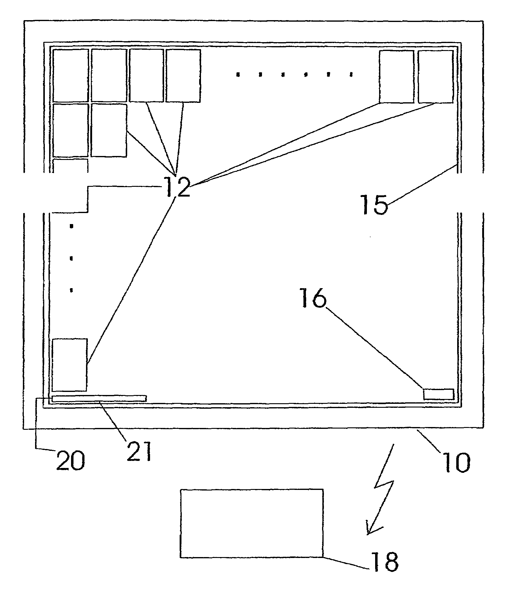
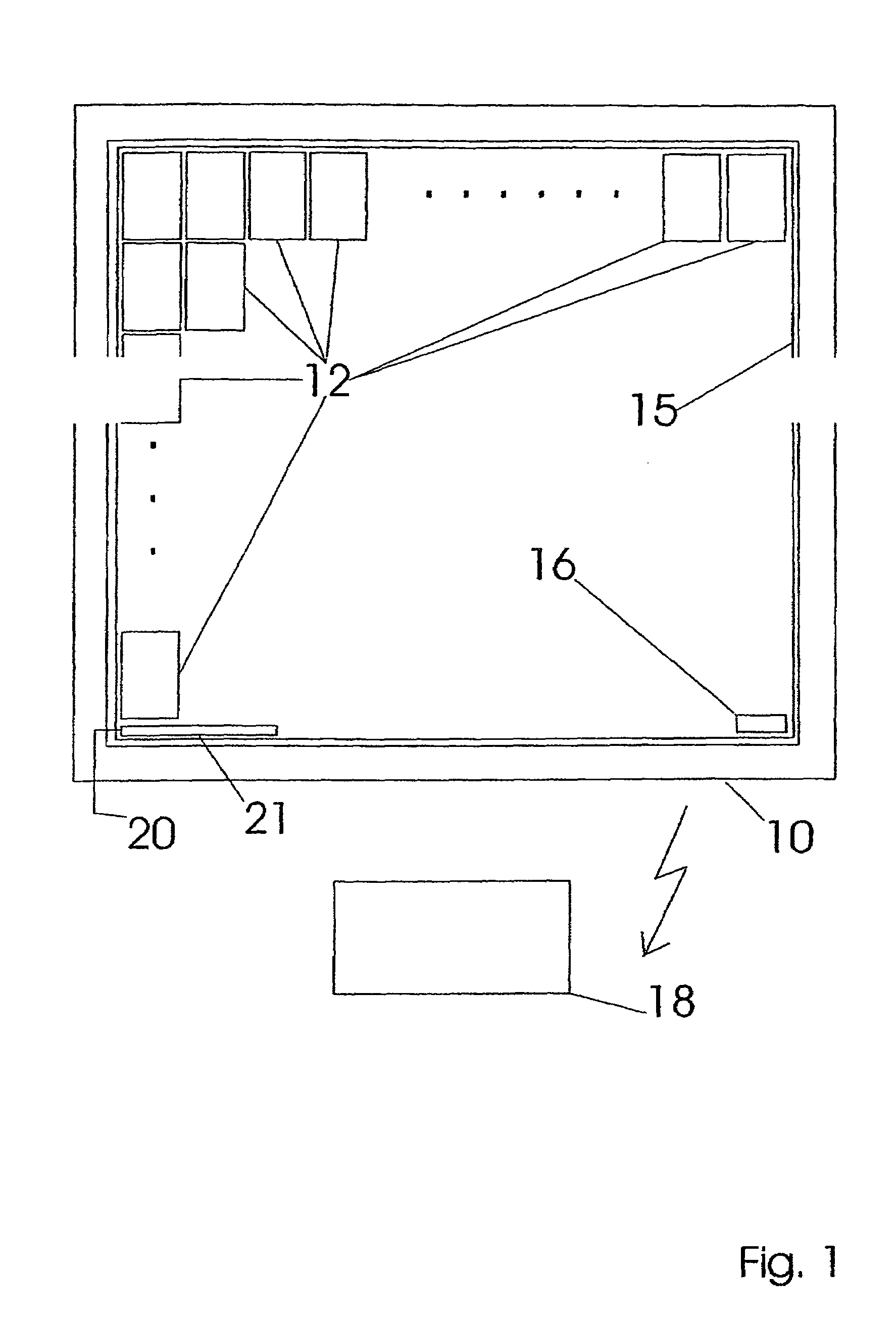
[0042]With reference to FIG. 1 and in addition with reference to FIG. 10 (cross section), a panel 15 according to the invention is shown containing a large number of individual modules 12 which are arranged like a matrix (in the form of an array), with the external dimensions of the panel 15 corresponding approximately to the dimensions of the visible area of a window surface, which is arranged within a window frame 10. As FIG. 10 additionally shows, the panel 15 is arranged in the interior between an outer glass pane 90 and an inner glass pane 92. The individual modules 12 themselves once again contain a large number of optically reflectively acting micromirrors, which are likewise arranged like a matrix in regular rows and columns on a common mounting surface, although this is not illustrated in FIG. 1, in order to improve the clarity. As can likewise be seen from FIG. 1, the ind...


PUM


Abstract

The invention relates to a microstructured technological system and, in particular, micromirror arrangements. The aim of the invention is to produce facade elements for buildings having large areas in square centimetres and above, at reduced cost. The entire micromirror arrangement can be produced as a flat, architectonically useable structural element in a modularly replicable manner. According to the invention, the control electronic system, which contains the logics which are controlled as mirror elements, is arranged in the centre of a control device at a specific, remote distance from which an addressing network is used to control the individual mirror elements or modules. Said addressing network is already integrated into the flat modules during production and to a large degree, in the form of printed lines. As a result, the necessity of incorporating silicon-based chip technology into the facade elements, which is expensive, is no longer necessary. Also, essentially less expensive materials than highly pure silicon are used in the production of the micromirror arrangements. Production costs, which are at least in the same size order as other, traditional, high quality façade elements, result therefrom.

Description

CROSS REFERENCE TO RELATED APPLICATIONS[0001]The present application is a 35 U.S.C. §371 National Phase conversion of PCT / DE2004 / 002720 filed Dec. 13, 2004, which claims priority of German Patent Application No. 103 58 967.8 filed Dec. 15, 2003 which is herein incorporated by reference. The PCT International Application was published in the German language.BACKGROUND OF THE INVENTIONPrior Art[0002]The present invention relates to microstructure technologies and in particular to micromirror arrangements. In particular, the invention relates to a micromirror apparatus and micromirror arrays.[0003]These micromirror arrays are specifically designed arrangements of miniaturized mirrors with a size in the order of magnitude of a few square micrometers. They are widely used as three-dimensional light modulators. In detail, micromirror arrays such as these and as disclosed in EP 0 877 272 contain a plurality of individual bodies which are connected to a common base mounting surface, in whic...

Claims


Application Information

Patent Timeline
Patent Type & Authority Patents(United States)
IPC IPC(8): G02B5/08E06B3/67E06B9/386F24J2/40F24S23/77G02B26/08
CPCE06B9/386F24J2/16F24J2/38F24J2/40F24J2/54G02B26/0841F24J2002/1066Y02B10/20Y02E10/47F24S50/20F24S2023/85F24S30/40F24S23/77F24S50/00
Inventor HILLMER, HARTMUTSCHMID, JURGENSTADLER, INGO
Owner WAITZ VON ESCHEN FRIEDRICH
Why Eureka
Try Eureka