
Motor control apparatus and method of assembling motor control apparatus

a motor control and motor control technology, applied in the direction of electrical apparatus construction details, lighting and heating apparatus, solid-state devices, etc., can solve the problems of reducing the size of the motor control apparatus, reducing the number of components and assembly man-hours, and limiting the implementation of a decrease in the insulation distance of the insulation distance, so as to reduce the number of substrate attaching screws, reduce the number of components and reduce the heat radiation from the heat sink. , the effect of reducing th

Inactive Publication Date: 2010-03-16
YASKAWA DENKI KK
View PDF15 Cites 17 Cited by
  • Summary
  • Abstract
  • Description
  • Claims
  • Application Information

AI Technical Summary

Benefits of technology

The invention aims to solve the problems of conventional motor control apparatuses by reducing their size and improving their assembly properties. The technical effects of the invention include reducing the insulation distance between the heat sink and the substrate, simplifying the process of aligning the power semiconductor module with the substrate, and reducing the time required for assembly.

Problems solved by technology

(1) The motor control apparatus is operated through a high voltage AC power supply such as AC200V or AC400V. Therefore, it is necessary to sufficiently maintain an insulation distance between the heat sink and the substrate and that between the heat sink and the power semiconductor module. There is a limit in an implementation of a decrease in these insulation distances in order to obtain a reduction in a size of the motor control apparatus.
(2) The power semiconductor module is temporarily fixed to the heat sink and the terminal of the power semiconductor module is aligned with the through hole of the substrate, and then, the substrate is fastened and fixed with the screw. For this reason, a long time is taken for aligning the terminal of the power semiconductor module with the through hole of the substrate.

Method used


Image

  • Motor control apparatus and method of assembling motor control apparatus
  • Motor control apparatus and method of assembling motor control apparatus
  • Motor control apparatus and method of assembling motor control apparatus

Examples


first example

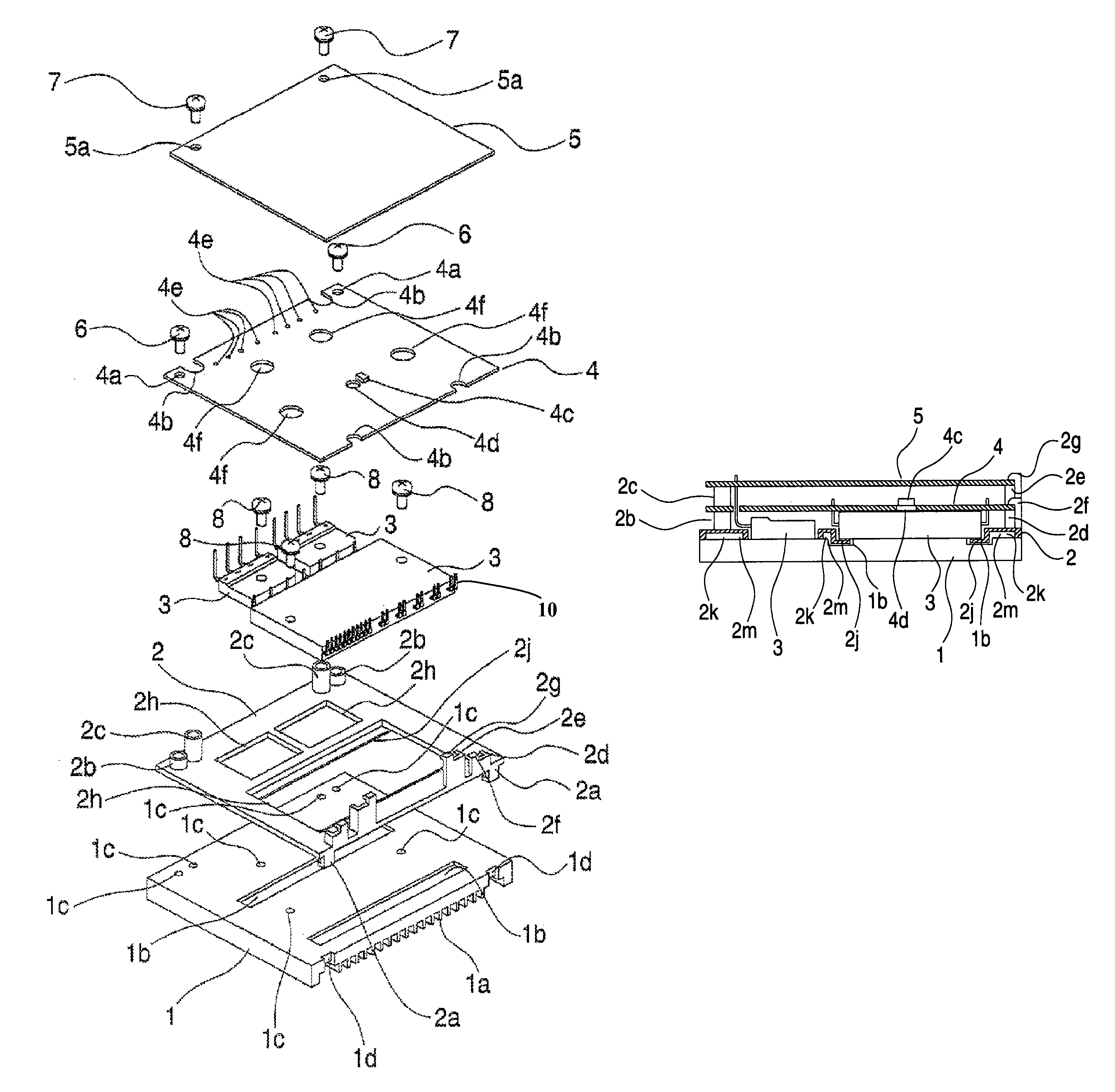
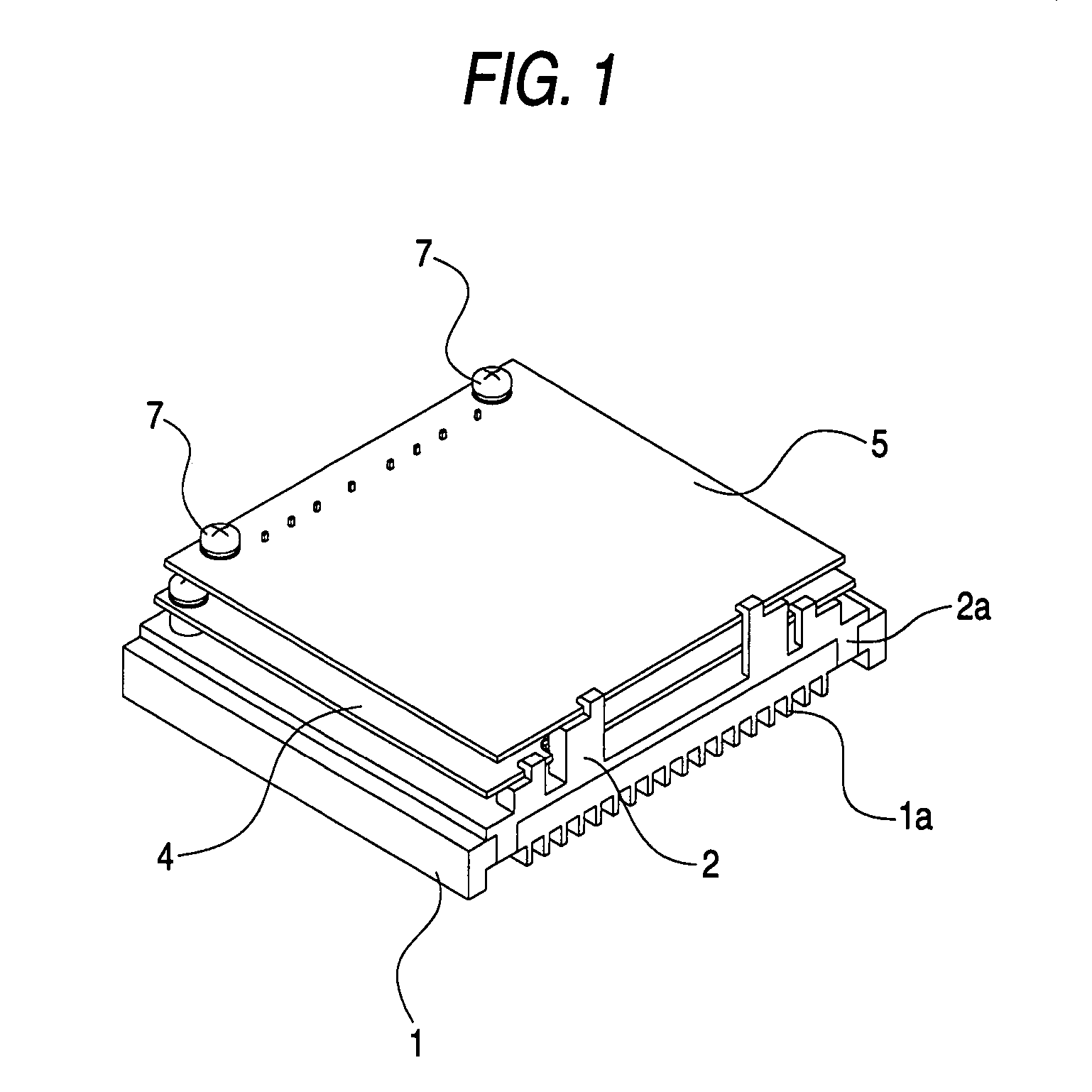
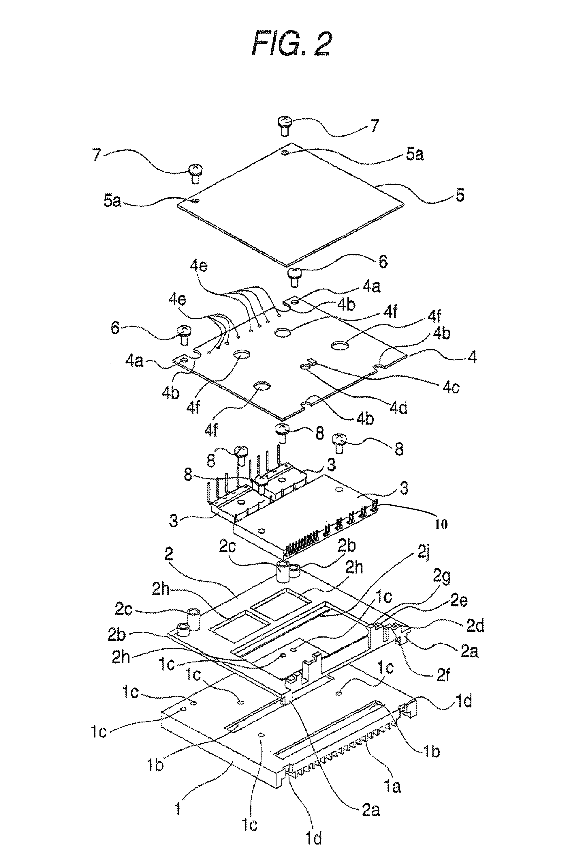
[0088]FIG. 1 is a perspective view showing a motor control apparatus according to the invention. FIG. 2 is an exploded perspective view showing the motor control apparatus in FIG. 1. FIG. 3A is a plan view showing a spacer in FIG. 1. FIG. 3B is a front view showing a spacer in FIG. 1. FIG. 4 is a schematic sectional view showing the motor control apparatus in FIG. 1.

[0089]In FIGS. 1 to 4, 1 denotes a heat sink, 2 denotes a spacer integrated and constituted by an adiabatic resin having a low thermal conductivity, for example, and 3 denotes a power semiconductor module such as an IGBT or a diode, which has such a structure that a plurality of terminals is protruded exactly transversely from a side surface and is extended upward in a middle, for example. 4 denotes a first substrate and 5 denotes a second substrate.

[0090]The heat sink 1 takes a shape of a rectangular parallelepiped, for example, and an upper surface is formed like a plane and a lower surface has a fin 1a formed thereon....


PUM

PropertyMeasurementUnit
heightaaaaaaaaaa
heightsaaaaaaaaaa
temperatureaaaaaaaaaa

Abstract

There is provided a motor control apparatus in which a size of the apparatus can easily be reduced, a work for aligning a power semiconductor module with a substrate can be eliminated and an assembling property can be enhanced.In a motor control apparatus in which a power semiconductor module adhering to a heat sink is mounted on a first substrate, a spacer is provided between the heat sink and the substrate and the power semiconductor module is disposed in the spacer. Moreover, an edge part of a hole has such a structure as to block a space between a terminal protruded from a side portion of the power semiconductor module and the heat sink.

Description

TECHNICAL FIELD[0001]The present invention relates to a motor control apparatus such as an inverter apparatus or a servo pump and a method of assembling the same, and more particularly to a structure for positioning and attaching a power semiconductor module to a substrate.BACKGROUND ART[0002]A motor control apparatus, for example, an inverter apparatus uses a power semiconductor module for generating high heat. For this reason, the power semiconductor module is caused to adhere to a heat sink, thereby producing a cooling effect (for example, see Patent Document 1).[0003]A conventional motor control apparatus, for example, a conventional inverter apparatus is constituted as shown in FIGS. 5 and 6.[0004]In FIGS. 5 and 6, 11 denotes a heat sink which has a stud 12 on four corners, for example, and a substrate 15 is mounted on the stud 12 and is fixed thereto with a screw 16. A power semiconductor module 13 such as an IGBT (Insulated Gate Bipolar Transistor) and a temperature sensor 14...

Claims


Application Information

Patent Timeline
Patent Type & Authority Patents(United States)
IPC IPC(8): H05K7/20F28F7/00H02M1/00
CPCH02M7/003H05K7/209Y10T29/49002H01L2924/0002H01L2924/00
Inventor ISOMOTO, KENJINOHARA, SHUHEINAGATOMO, SHIGEKATSU
Owner YASKAWA DENKI KK
Learn More