Test precondition items for automated analysis and test generation

Active Publication Date: 2010-03-16
THE MATHWORKS INC
View PDF0 Cites 40 Cited by
  • Summary
  • Abstract
  • Description
  • Claims
  • Application Information

AI Technical Summary

Benefits of technology

[0008]The precondition design element may be used to limit verification to the more meaningful or practical scenarios of the behavior of the system under design. Furthermore, the precondition design element may improve the performance of verification by reducing the combinations or occurrences of executions to provide the desired verification coverage. Additionally, the precon

Problems solved by technology

Running comprehensive or multiple verification scenarios in a verification tool may be time consuming and resource intensive.
The techniques and methods used by the verification tool may exercise behavior or functionality that is not of concern to the model-based designer or that is not practical or realistic in the intended application of the implementation of the model-based design.
Therefore, it may be time consuming, resource in

Method used


Image

  • Test precondition items for automated analysis and test generation
  • Test precondition items for automated analysis and test generation
  • Test precondition items for automated analysis and test generation

Examples


Embodiment Construction

[0039]Certain embodiments of the present invention are described below. It is, however, expressly noted that the present invention is not limited to these embodiments, but rather the intention is that additions and modifications to what is expressly described herein also are included within the scope of the invention. Moreover, it is to be understood that the features of the various embodiments described herein are not mutually exclusive and can exist in various combinations and permutations, even if such combinations or permutations are not expressly made herein, without departing from the spirit and scope of the invention.

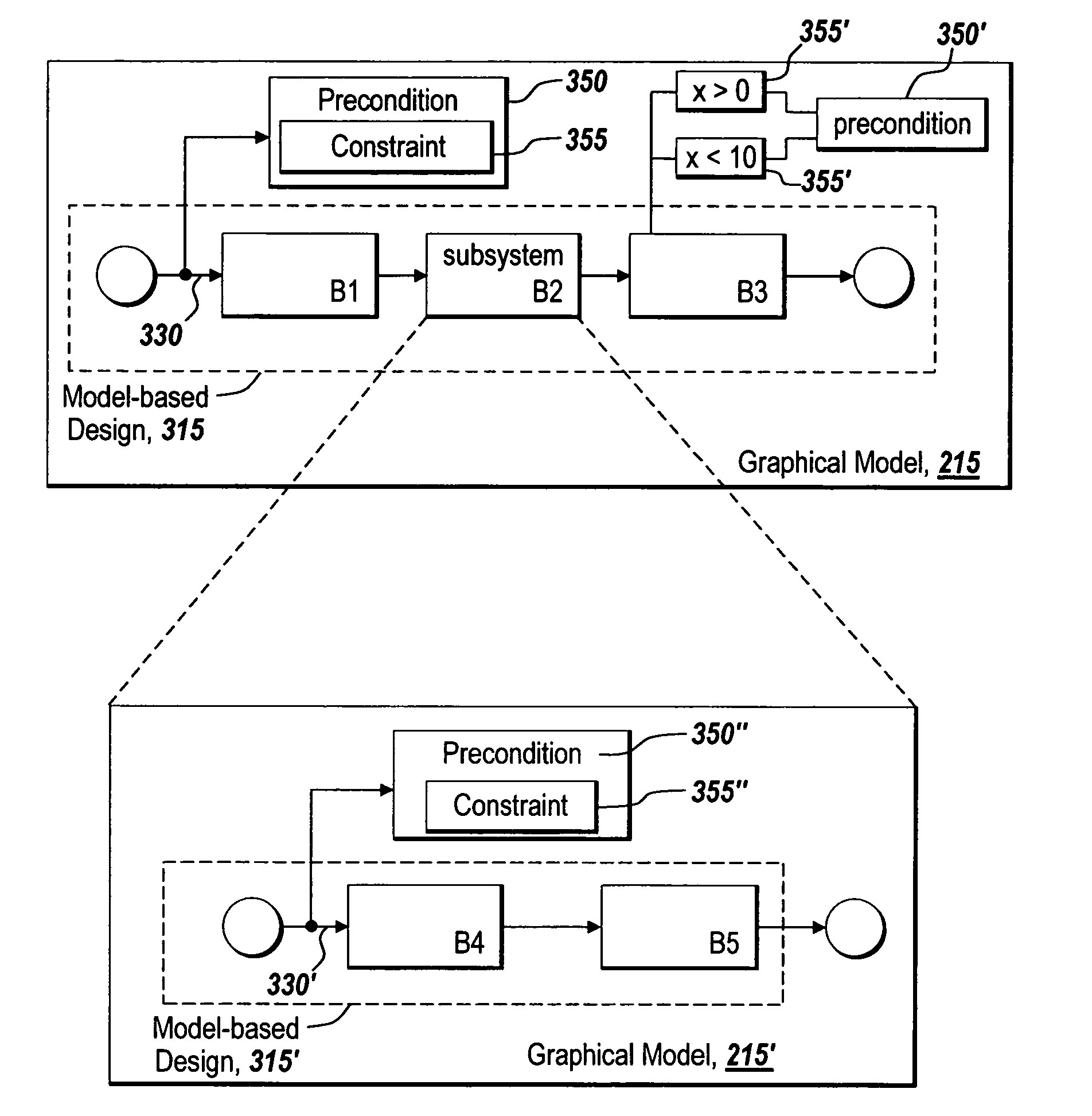
[0040]The illustrative embodiment of the present invention provides systems and methods for using a design element in a graphical model to represent and identify a precondition for use by a verification tool in verifying an executable form of the design represented by the graphical model. A precondition design element provides a specification of a constraint to b...


PUM


Abstract

The present invention provides methods and systems for using a design element in a graphical model to represent and identify a precondition for use by a verification tool in verifying an executable form of the design represented by the graphical model. The precondition design element provides a specification of a verification constraint without affecting the behavior of the design. The constraint is to be applied by the verification tool in verifying the design. As such, the precondition design element of the present invention provides a mechanism and formalism in a model-based design approach that is used to constrain automatically generated tests or verification of the design represented by the graphical model.

Description

TECHNICAL FIELD[0001]The present invention generally relates to associating a precondition design element with a model-based design represented by a graphical model for use by a verification tool in verifying the model-based design.BACKGROUND INFORMATION[0002]Graphical modeling environments, such as the technical computing and block diagram modeling environment of MATLAB® and Simulink® from the MathWorks, Inc. of Natick, Mass., can provide a “model-based design” approach to designing an implementation, such as for embedded computational hardware. The term “model-based design” is used to refer to a graphical model acting as a design or a specification for implementation. A model-based design may be used as a design specification for an implementation, such as an implementation of an algorithm in hardware circuitry, the implementation of code to run on a microprocessor, or software to run in a network environment.[0003]A graphical modeling environment can produce model-based designs i...

Claims


Application Information

Patent Timeline
IPC IPC(8): G06F17/50
CPCG06F8/34
Inventor ALDRICH, WILLIAM J.
Owner THE MATHWORKS INC
Why Eureka
Try Eureka