
Structure for capacitive balancing of integrated relative humidity sensor

a capacitive balancing and relative humidity technology, applied in the direction of variable capacitors, resistance/reactance/impedence, instruments, etc., can solve the problems of erroneous readings, dispersion effect, and elements utilized as resistive components, so as to improve the capacitive balancing structure, improve the accuracy of humidity measurement, and avoid additional costs

Active Publication Date: 2010-03-23
HONEYWELL INT INC
View PDF9 Cites 9 Cited by
  • Summary
  • Abstract
  • Description
  • Claims
  • Application Information

AI Technical Summary

Benefits of technology

[0017]It is another aspect of the present invention to provide for an improved structure for capacitive balancing of relative humidity sensors in the presence of water and / or moisture condensation.
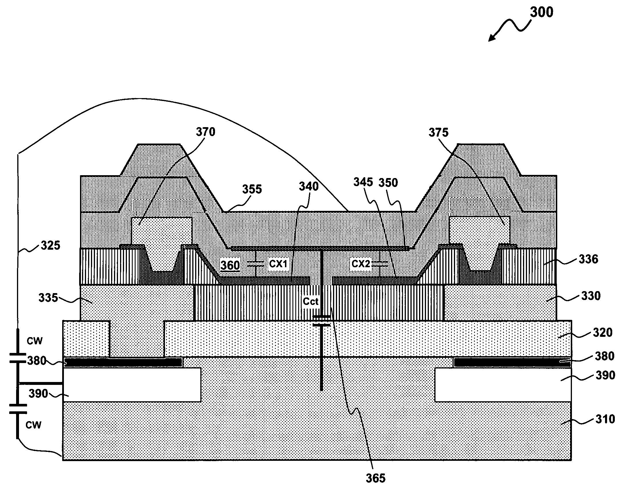
[0018]The aforementioned aspects and other objectives and advantages can now be achieved as described herein. An improved relative humidity sensor for more accurate measurement of humidity in the presence of water condensation is disclosed. The relative humidity sensor generally includes a pair of electrodes with a gap-interposed therebetween to form series sensing capacitors on a silicon substrate with a silicon oxide film configured on a surface. A moisture-sensitive structure can be provided so as to cover the pair of capacitor plates with a silicon nitride film interposed therebetween. A P-well and a P-plus layer can be added to the perimeter of the substrate to create a path for a parasitic capacitance caused by water condensation to connect to one node of the sensing capacitor. Because the P-well and P-plus layers are already included in the normal fabrication procedure, there is no additional cost incurred to include these layers around the perimeter of the sensor die.
[0019]The capacitance formed between the two electrodes changes in accordance with ambient humidity. The humidity sensing capacitor structure design disclosed herein can therefore increase the total capacitance value in the presence of water condensation on the sensing element and thereby give a more accurate measurement of humidity. The structure and the P-well and P-plus layers can be fabricated utilizing standard silicon wafer processing techniques commonly used on existing relative humidity sensors. The improved structure proposed in this invention is accomplished utilizing only photo-mask changes in the wafer fabrication process flow so that no additional processing cost is incurred.

Problems solved by technology

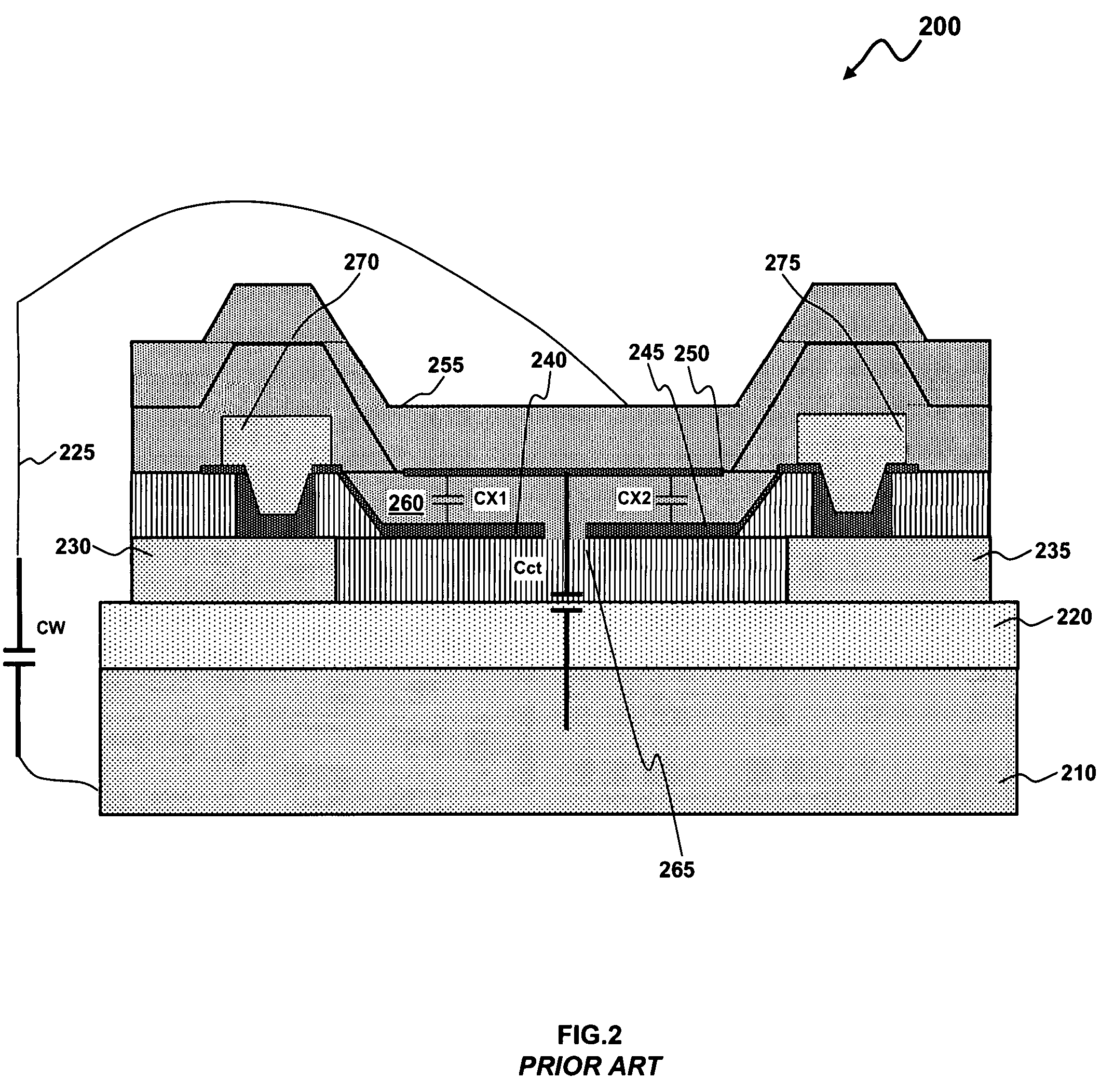
It has been found, however, that elements utilized as resistive components suffer from the disadvantage that there is an inherent dissipation effect caused by the dissipation of heat due to the current flow in the elements necessary to make a resistance measurement.
The result includes erroneous readings, among other problems.
In addition, there can also be inaccuracy incurred at high relative humidity values where high water content causes problems due to excessive stress and the resulting mechanical shifts in the components of the element.
Small temperature fluctuations near the sensor can unknowingly cause condensation to form when operating at humidity levels above 95%.
This effect causes the total capacitance value CTotal to decrease, and therefore generates an erroneous low humidity value.
As shown in equation (2), the total capacitance value CTotal decreases due to the presence of water condensation, which results in an inaccurate measurement of humidity.
These can be useful, but limitations in cost and packaging do not always allow for these solutions.

Method used


Image

  • Structure for capacitive balancing of integrated relative humidity sensor
  • Structure for capacitive balancing of integrated relative humidity sensor
  • Structure for capacitive balancing of integrated relative humidity sensor

Examples


Embodiment Construction

[0024]The particular values and configurations discussed in these non-limiting examples can be varied and are cited merely to illustrate at least one embodiment and are not intended to limit the scope thereof.

[0025]Referring to FIG. 3, a cut-away side view of an improved relative humidity sensor apparatus 300 is illustrated, in accordance with a preferred embodiment. It should be understood that there are other integrated components of the sensor that are not depicted in the figure. The humidity sensor apparatus 300 depicted in FIG. 3 can be used for humidity control in an air conditioner or to detect humidity for weather observation purposes. It is understood, however, that a wide variety of other applications for humidity sensor apparatus 300 can also be implemented, depending upon design goals and considerations. As depicted in FIG. 3, an N-type silicon substrate 310 can be employed as a semiconductor substrate 310. A silicon oxide film 320 can be formed on the semiconductor subs...


PUM


Abstract

An improved relative humidity sensor apparatus that provides a more accurate measurement of humidity in the presence of water condensation. A series capacitive sensor includes a thin porous platinum top plate, a humidity sensitive polyimide dielectric, and two metal bottom plates on a semiconductor substrate. The two capacitors can be wired in series such that the metal bottom plates form independent, electrically driven connections. The thin top layer can form a top plate. Changes in humidity affect the humidity sensitive dielectric thereby causing changes in the capacitive value. A P-well layer and a P-plus layer can be added at the perimeter of the substrate to create a path for a parasitic capacitance caused by water condensation to connect to one or more connection nodes, thereby preventing erroneous measurements of humidity in the presence of water condensation.

Description

TECHNICAL FIELD[0001]Embodiments are related to semiconductor wafer-based devices. Embodiments are also related to relative humidity sensors. Embodiments are additionally related to relative humidity sensor structures for the accurate measurement of humidity.BACKGROUND OF THE INVENTION[0002]Humidity plays a very major role in various industrial and commercial applications. Monitoring and controlling humidity is of great importance for the reliable operation of various systems. For example, solid-state semiconductor devices are found in most electronic components today. Semiconductor-based sensors are fabricated using semiconductor processes. Humidity sensors represent but one class of semiconductor-based sensors finding a useful industrial application. Modern manufacturing processes, for example, generally require measurement of moisture contents corresponding to dew points between −40° C. and 180° C., or a relative humidity between 1% and 100%. There is also a need for a durable, c...

Claims


Application Information

Patent Timeline
Patent Type & Authority Patents(United States)
IPC IPC(8): G01R27/26H01G5/012
CPCG01N27/223
Inventor ALIMI, YOUSEF M.DAVIS, RICHARD A.
Owner HONEYWELL INT INC
Learn More