Electric motor comprising an electronic unit with a punched grid

a technology of electric motor and electronic unit, applied in the field of electric motor, can solve problems such as cost advantages

Inactive Publication Date: 2010-03-30
ROBERT BOSCH GMBH
View PDF25 Cites 3 Cited by
  • Summary
  • Abstract
  • Description
  • Claims
  • Application Information

AI Technical Summary

Benefits of technology

[0004]In contrast, the electric motor in accordance with the invention has the advantage that, because of the embodiment of a substrate as a punched grid with extensions, which protrude from the sprayed on plastic body, the electronic unit directly makes electrical and mechanical connections available, which are embodied to be so stable that additional components of the electric motor can be attached directly to the electronic unit. The advantage of this is that the electronic module in the motor construction space can be integrated directly on the armature shaft in the motor, thereby eliminating additional electrical connections and mechanical holders for specific motor components.
[0005]The advantage of the method in accordance with the invention for producing an electric motor with an electronic control unit is that, by connecting a mechanically stable punched grid with a ceramic substrate in a sandwich construction, very powerful and compact control electronics can be produced in a cost-effective and easily variable process. Because of directly connecting motor components to the control unit, additional process steps are eliminated since additional motor components, such as brush holders, shielding surfaces, connector pins and connections to external electric components, are final mounted when the electronic unit is assembled.

Problems solved by technology

In addition, because of the sandwich structure and the use of bare die components, the dimensions of the substrates can be designed to be smaller as compared with standard technologies, which results in cost advantages despite using a logic substrate that is more expensive as compared with a printed circuit board.

Method used


Image

  • Electric motor comprising an electronic unit with a punched grid
  • Electric motor comprising an electronic unit with a punched grid
  • Electric motor comprising an electronic unit with a punched grid

Examples


Embodiment Construction

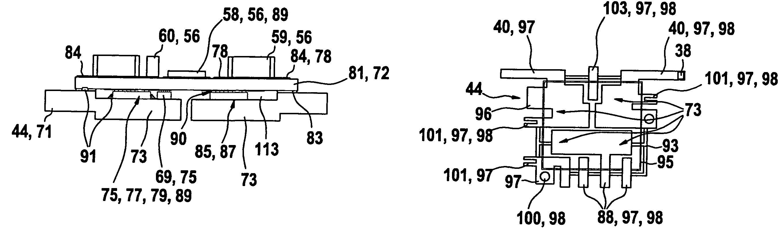
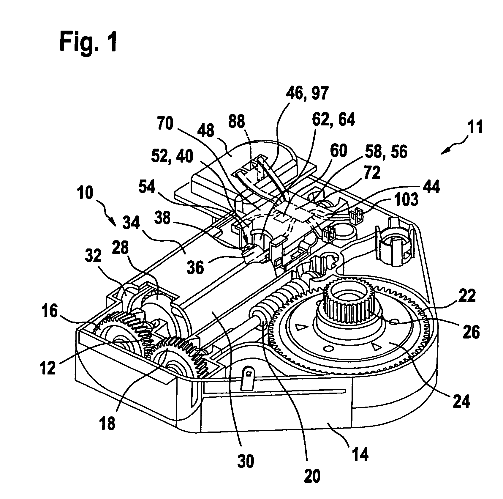
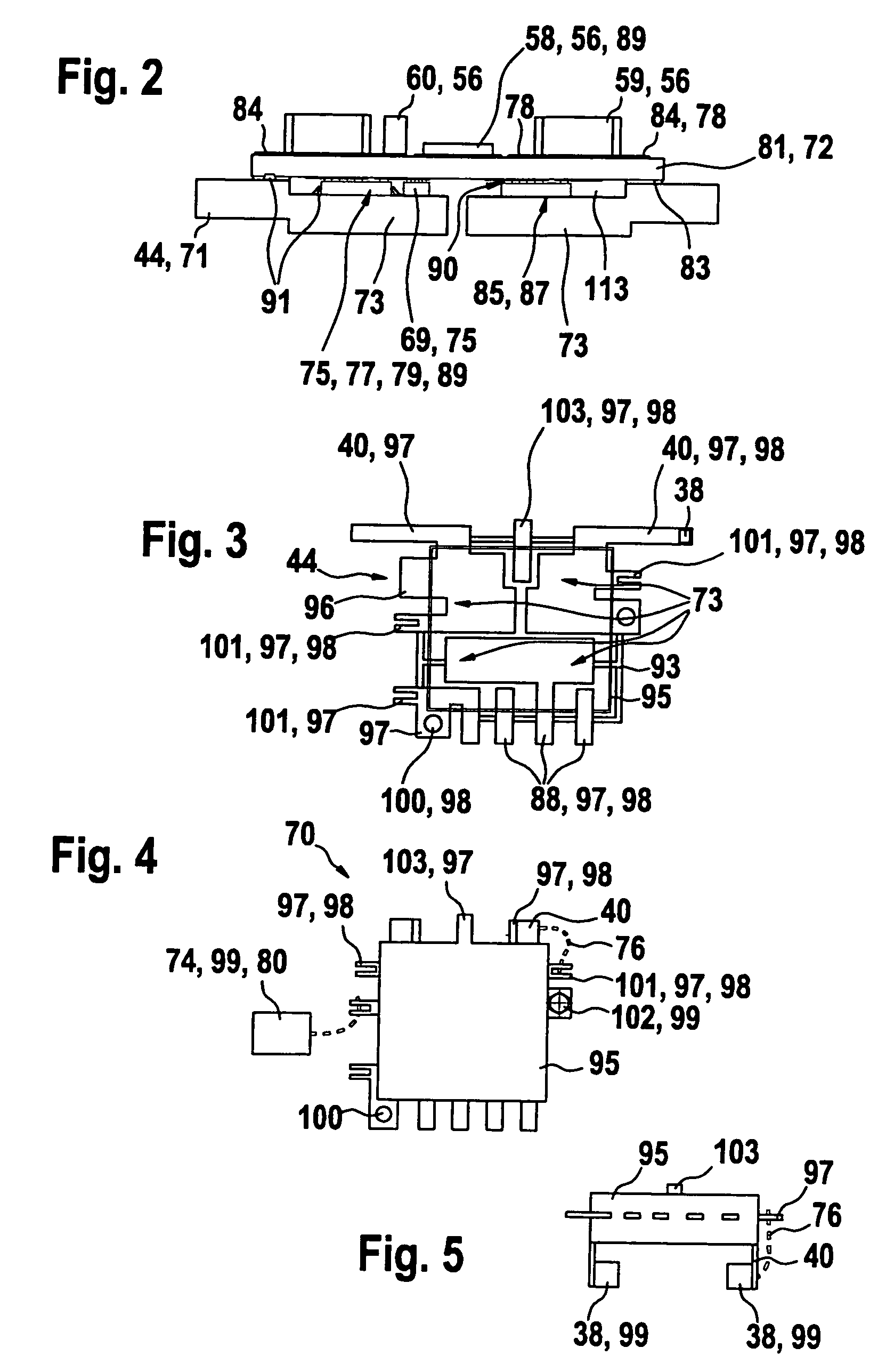
[0053]FIG. 1 depicts a gear drive unit 11, in which an electric motor 10 with an armature shaft 12 is positioned over its entire length in a first housing part 14. Positioned on the armature shaft 12 is a first gear element 16, which is coupled with second gear element 18 of a separate worm shaft 20. The worm shaft 20 meshes with a worm wheel 22, which further directs the driving torque over a damping device 24 to an output gear 26, which drives a window or a sun roof in a motor vehicle for example. A rotor 28 is arranged on the armature shaft 12 and this rotor can rotate freely within a housing-mounted stator 30. The stator 30 features permanent magnets 32, which are connected with one other by means of a two-part magnetic yoke element 34. The armature shaft 12 features a commutator 36 for energizing purposes, which has a frictional connection with carbon brushes 38, which are connected to an electronic module 70 via spring clips 40. The electronic module 70 has a conductive punche...


PUM


Abstract

Electric motor (10), in particular for adjusting moving parts in a motor vehicle, comprising an electronic unit (70) with a sandwich construction, which contains a first electrically conductive substrate (71) and a second electric conductive substrate (72), between which power components are located and electrically connected to both substrates (71, 72), and a side (84) of the second substrate (72) facing away from the first substrate (71) is equipped with additional electronic components (56), wherein the first substrate (71) is embodied as a punched grid (44), which together with the second substrate (72) is extrusion coated with a plastic body (95) in such a way that the extensions (97) of the punched grid (44) protrude from the plastic body (95), forming an electrical and / or mechanical interface (98) for connecting additional motor components (99, 38, 40, 104, 102, 80).

Description

BACKGROUND OF THE INVENTION[0001]The invention relates to an electric motor, in particular for adjusting moving parts in a motor vehicle as well as a method for producing said electric motor.[0002]A power semi-conductor module was disclosed in DE 34 06 528 A1 in which at least one semi-conductor element is arranged between two parallel substrates and makes contact with a metallization on the substrates. Ceramic plates are used as substrates, on which all power connections are applied in the form of metallic conductor tracks. The power semi-conductor in this case module can be placed in a housing, which is at least partially filled with an encapsulating material.[0003]If such a semi-conductor module is supposed to be used for triggering an electric motor, then, based on the use of the two metallized ceramic substrates, it forms a separate electronic unit, which cannot be integrated directly into the construction space of the motor housing since it can only make electrical contact wit...

Claims


Application Information

Patent Timeline
Patent Type & Authority Patents(United States)
IPC IPC(8): H02K11/00H01L23/498H01L25/07H01L25/16
CPCH01L23/49861H01L25/071H01L25/072H01L25/16H01L2924/0002H01L2924/09701H01L2924/00
Inventor URBACH, PETERFEILER, WOLFGANGRAICA, THOMASHORNUNG, STEFAN
Owner ROBERT BOSCH GMBH
Why Eureka
Try Eureka