
Rotary position detector and associated methods

Active Publication Date: 2010-03-30
BENNER JR WILLIAM R
View PDF14 Cites 33 Cited by
  • Summary
  • Abstract
  • Description
  • Claims
  • Application Information

AI Technical Summary

Benefits of technology

[0026]The current invention is directed to an optical position detector that provides low inertia operation and can be used with small optical scanners. Unlike other known position detectors, the current invention provides improved signal-to-noise ratio and absolute position accuracy.

Problems solved by technology

Therefore, one of the limiting factors of accuracy and repeatability is the performance of the position detector used with the optical scanner.
If the position detector produces some output as a result of axial or radial shaft motion, the servo controller will mistakenly interpret this errant output as a change in rotational position, resulting in a positioning error of the overall system.
Regardless of the type of position detector used, capacitive or optical, all known position detectors are believed to suffer from one common problem: They all output a signal that is indicative of relative shaft rotation, but they do not output a signal that is indicative of absolute shaft rotation.
The servo will then try to compensate for this, and generate an error.
However, the use of AGC is only good enough to correct first-order problems.
When implemented in a capacitive position detector, this technique has several parasitic problems.
First, capacitive position detectors are very sensitive to the shape of the plate members.
And whether this technique is used with an optical position detector or with a capacitive position detector, the specially shaped moving butterfly is more expensive to manufacture.
Analog servo systems have been used because they are relatively inexpensive and relatively simple, and also because up until now, digital servo systems could not achieve the high resolution and high sample rate necessary to be usable with the fastest galvanometer scanners.
Until recently, it was cost-prohibitive to implement a servo controller in a digital form with this high sample rate and resolution.
Although these last two are not servo parameters in the strictest sense, they certainly do affect servo performance and accuracy.
Because engineers may not be the end-users of systems with galvanometer scanners, any non-factory tuning can result in sub-optimal operation.
As discussed previously, with previously known position detectors, it is impossible for servos to know the position scale with absolute certainty; so it is impossible to make a digital servo that will completely auto-tune.
The problem with this approach is that these parameters can change over time.
The torque constant of the scanner depends on the magnetism of the rotor (or other scanner components), and this magnetism certainly changes with temperature, and, if the scanner is abused or overheated, can also change with time.
Position detector components also change with time due to component drift and also due to temperature and other environmental effects.

Method used


Image

  • Rotary position detector and associated methods
  • Rotary position detector and associated methods
  • Rotary position detector and associated methods

Examples


Embodiment Construction

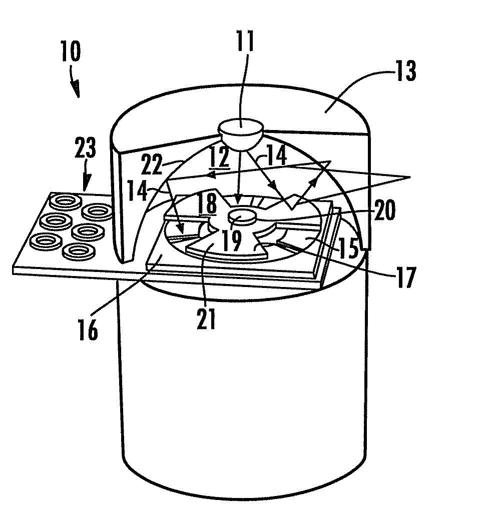
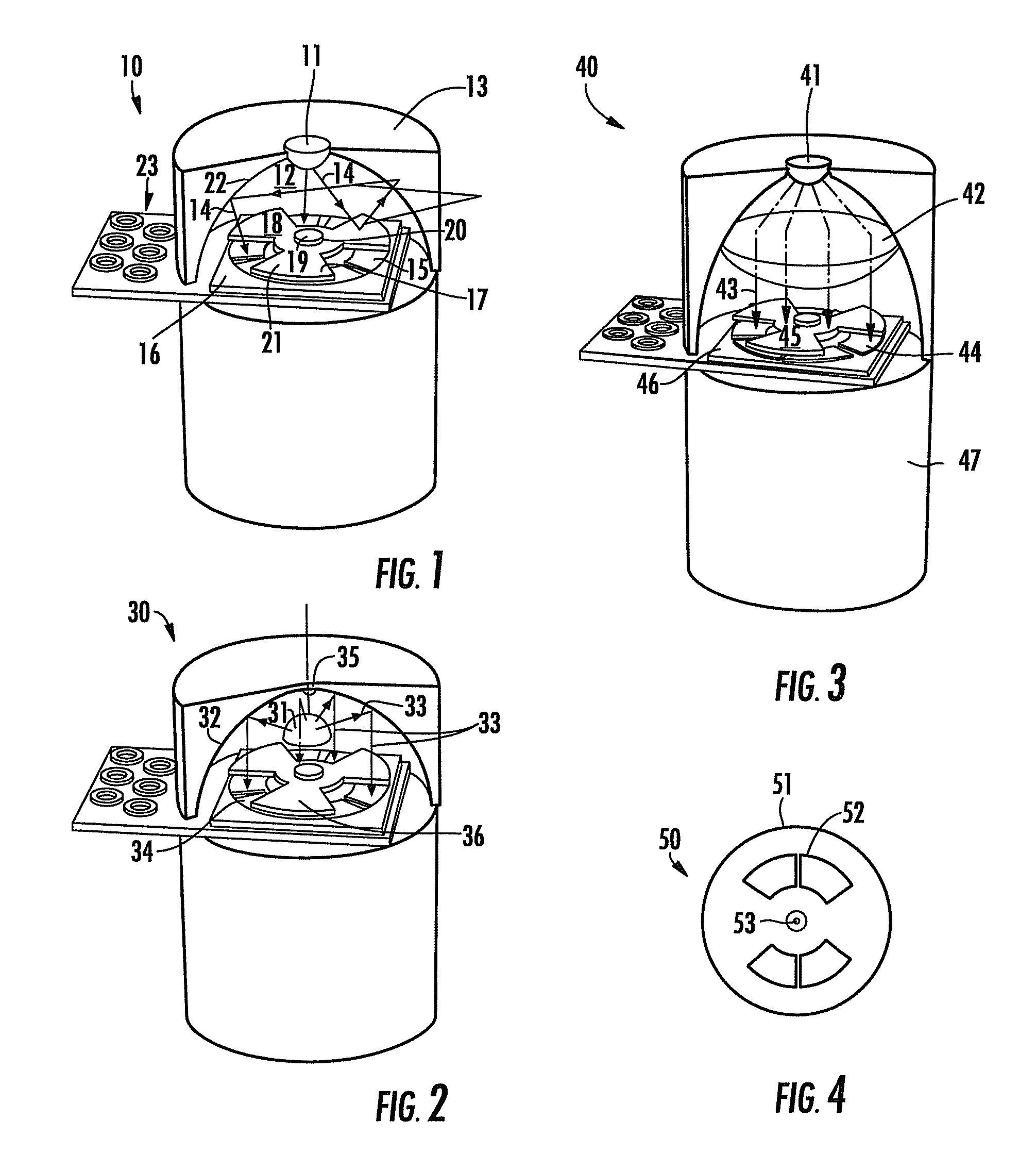
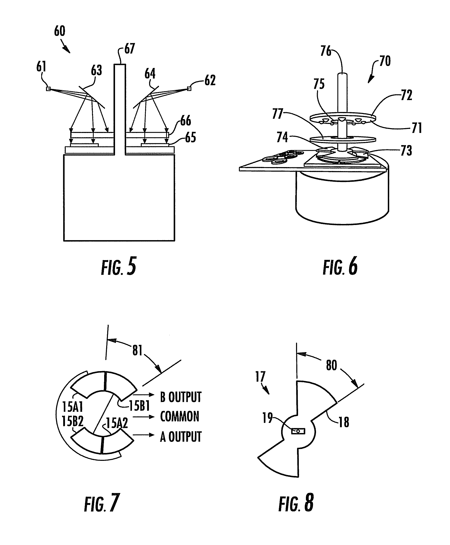
[0058]The present invention will now be described more fully hereinafter with reference to FIGS. 1-27, in which preferred embodiments of the invention are shown. Unless otherwise defined, all technical and scientific terms used herein have the same meaning as commonly understood by one of ordinary skill in the art to which this invention pertains. Although methods and materials similar or equivalent to those described herein can be used in the practice or testing of the present invention, suitable methods and materials are described below. Any publications, patent applications, patents, or other references mentioned herein are incorporated by reference in their entirety. In case of conflict, the present specification, including any definitions, will control. In addition, the materials, methods, and examples given are illustrative in nature only and not intended to be limiting. Accordingly, this invention may be embodied in many different forms and should not be construed as limited ...


PUM


Abstract

A rotary position detector includes a housing and a light source positioned to emit light rays onto a light detector assembly having a first number of toroidal-sector-shaped light sensors, which are disposed in “A,B” pairs about a motor shaft axis so that each “A” detector is circumferentially positioned between two “B” detectors. A light blocker is affixed for rotation with a motor shaft between the light detector assembly and light source and has a second number of opaque, pie-shaped elements arrayed about the shaft, the second number equal to one-half of the first number. An angular subtense of the light blocker elements is greater than that of a detector element. A signal connection between the light detector elements and a circuit measures a signal from the “A” and “B” detectors relating to an amount of light falling thereon, a difference therebetween related to an angular position of the shaft.

Description

CROSS-REFERENCE TO RELATED APPLICATION[0001]This application claims priority to provisional application Ser. No. 60 / 886,168, filed Jan. 23, 2007.BACKGROUND OF THE INVENTION[0002]1. Field of the Invention[0003]This invention relates to rotary position detectors for indicating the angular position of a shaft or other rotating element. More particularly, this invention relates to such position detectors used on motors and galvanometer-based optical scanners.[0004]2. Description of Related Art[0005]Rotary position detectors have many uses, such as detecting the position of the shaft on a motor, for the purpose of electrical commutation. Another such use is to detect the position of a tensioner pulley in a magnetic tape player or web-type printing press, for the purpose of maintaining a constant tension on the tape or paper. One of the more recent uses of a rotary position detector is to sense the position of the accelerator (gas) pedal in an automobile that uses electric motors as a par...

Claims


Application Information

Patent Timeline
IPC IPC(8): G01B11/26
CPCG01D5/342G01D5/3473G01D5/34776
Inventor BENNER, JR., WILLIAM R.
Owner BENNER JR WILLIAM R
Features
  • Generate Ideas
  • Intellectual Property
  • Life Sciences
  • Materials
  • Tech Scout
  • Unparalleled Data Quality
  • Higher Quality Content
  • 60% Fewer Hallucinations
Learn More