Throttle body spacer for use with internal combustion engines

a technology for internal combustion engines and throttle bodies, which is applied in the direction of combustion air/fuel air treatment, machines/engines, manufacturing tools, etc., can solve the problems of low fuel efficiency, low efficiency, and device performance of prior units giving jerky responses below fifty-five miles per hour, so as to reduce carbon deposits, reduce heat absorption, and reduce the effect of air transfer

Inactive Publication Date: 2010-04-06
GSP POWERSPACER
View PDF6 Cites 10 Cited by
  • Summary
  • Abstract
  • Description
  • Claims
  • Application Information

AI Technical Summary

Benefits of technology

[0011]Accordingly a throttle body spacer for effectively increasing horsepower, torque, and fuel efficiency in internal combustion engines is provided. It comprises a spacer block with a smooth bore hole, a plurality of air fins, each air fin being connected at one end to the spacer block and the distal end extending to about the center of the bore hole, and a means for mounting the throttle spacer body to hold it in place. The new throttle body spacer is formed of a thermoset resin which absorbs significantly less heat compared to the aluminum designs of the prior art. By keeping the inner air temperatures lower, cooler dense air is atomized with greater efficiency, which equates with increased horsepower and improved fuel economy. The bore hole(s) of the new apparatus are polished to a smooth, slick finish; so airflow passes through smoothly with no restrictions. The thickness, also referred to as the height, of the throttle body spacer is such that it increases the velocity and force of the air as it passes through the throttle body spacer and into the manifold.
[0012]To add to this equation, the air fins, which are narrow enough to let air pass through yet wide enough to still have sufficient structural strength, are bent at an angle such that they direct the air in a spiral motion, creating a spinning turbulence in the incoming air so that is has a much greater velocity as it enters the air intake manifold. The air fuel mixture is atomized with the motion of the air fins making it more efficient as it enters the engine. Putting the air fuel mixture to greater use, as it enters the engine, produces more horsepower, torque, and better fuel economy as less unburned fuel is left in the manifold. The air fin design and the smooth bore produce a smoother, quicker throttle response with increased horsepower at all engine speeds, whereas other designs only respond at lower speeds. Furthermore, the smooth design of the center hole further optimizes performance by reducing carbon deposit buildup.

Problems solved by technology

However, the prior art devices leave unburned fuel in the manifold so the devices fail to increase performance and have little if any effect on fuel efficiency.
Another drawback is that the devices of the prior unit give a jerky response below fifty-five miles per hour and fail to provide the desired results at speeds above fifty-five miles per hour, as well as at higher revolutions per minute (RPM).
These prior designs use aluminum material, which absorbs tremendous heat, reducing efficiency.
These indentations restrict and slow down the air flow, especially at speeds above fifty-five miles per hour, resulting in minimal performance gains.
The rigid surface also facilitates the accumulation of carbon deposits, which further slows air transition and reduces effectiveness.
The available products in the industry fail to overcome these deficiencies; they do not increase fuel efficiency and are only remotely useful at very slow speeds.

Method used


Image

  • Throttle body spacer for use with internal combustion engines
  • Throttle body spacer for use with internal combustion engines
  • Throttle body spacer for use with internal combustion engines

Examples


Embodiment Construction

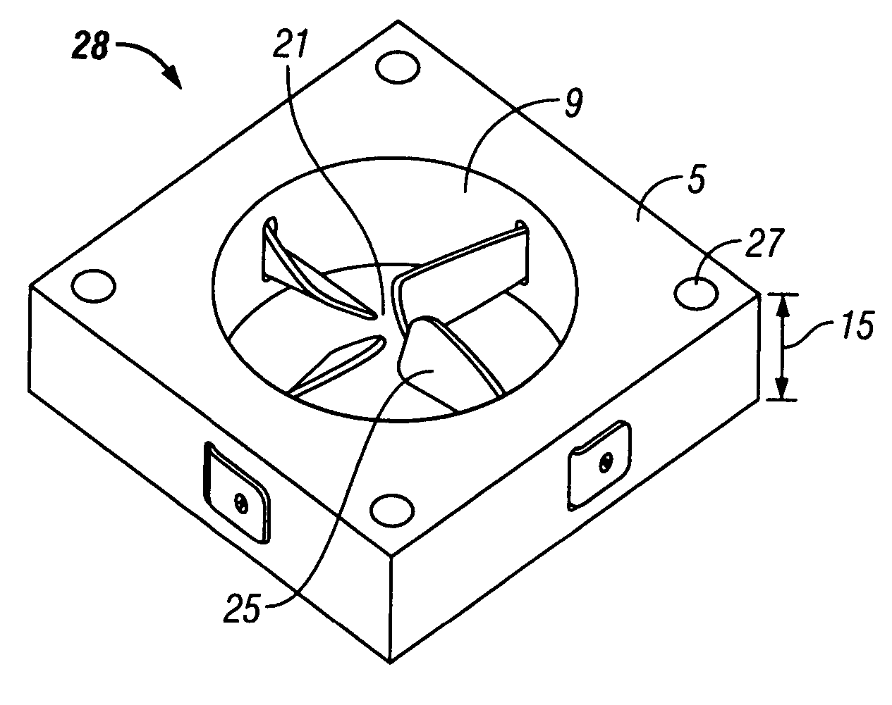
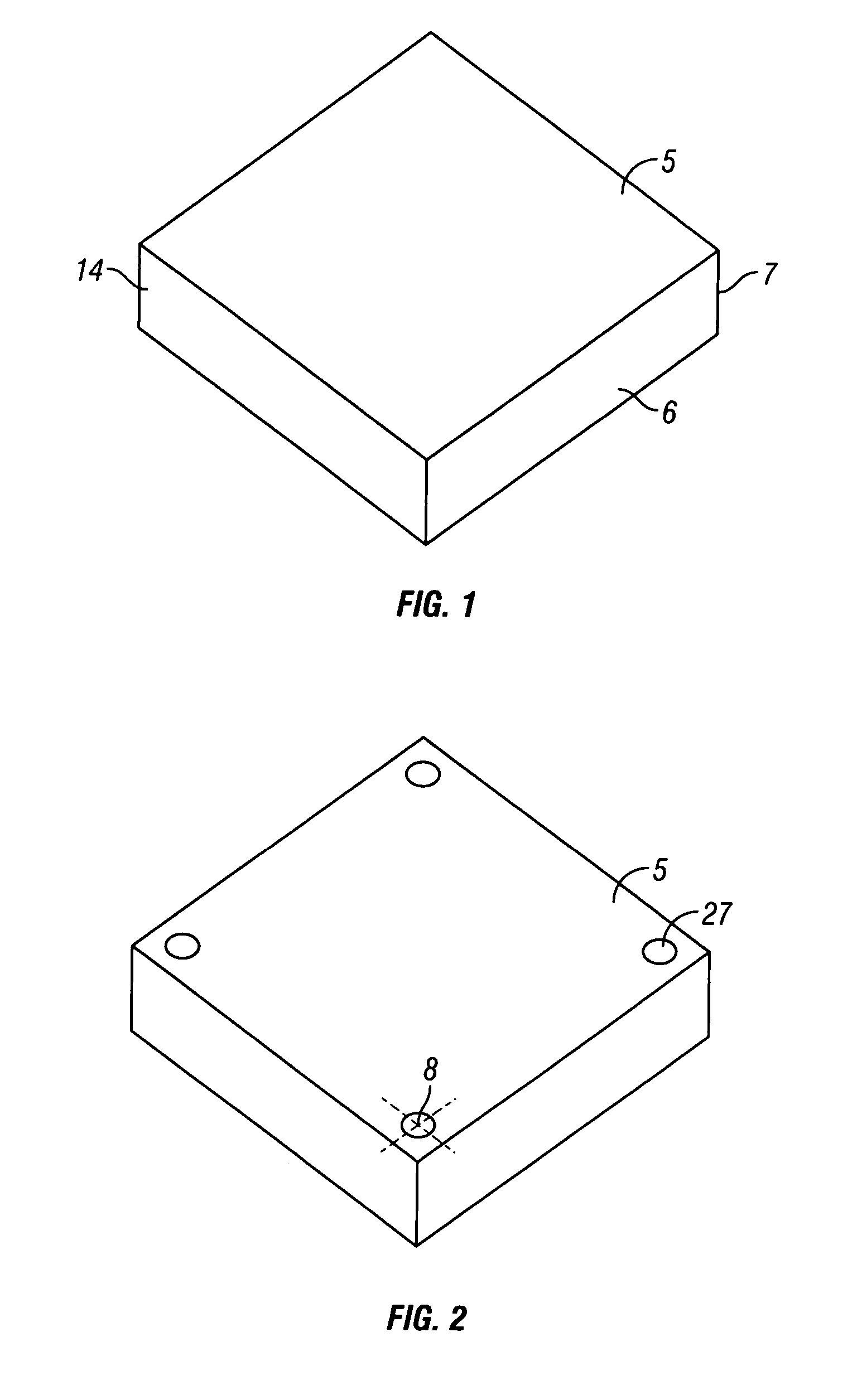
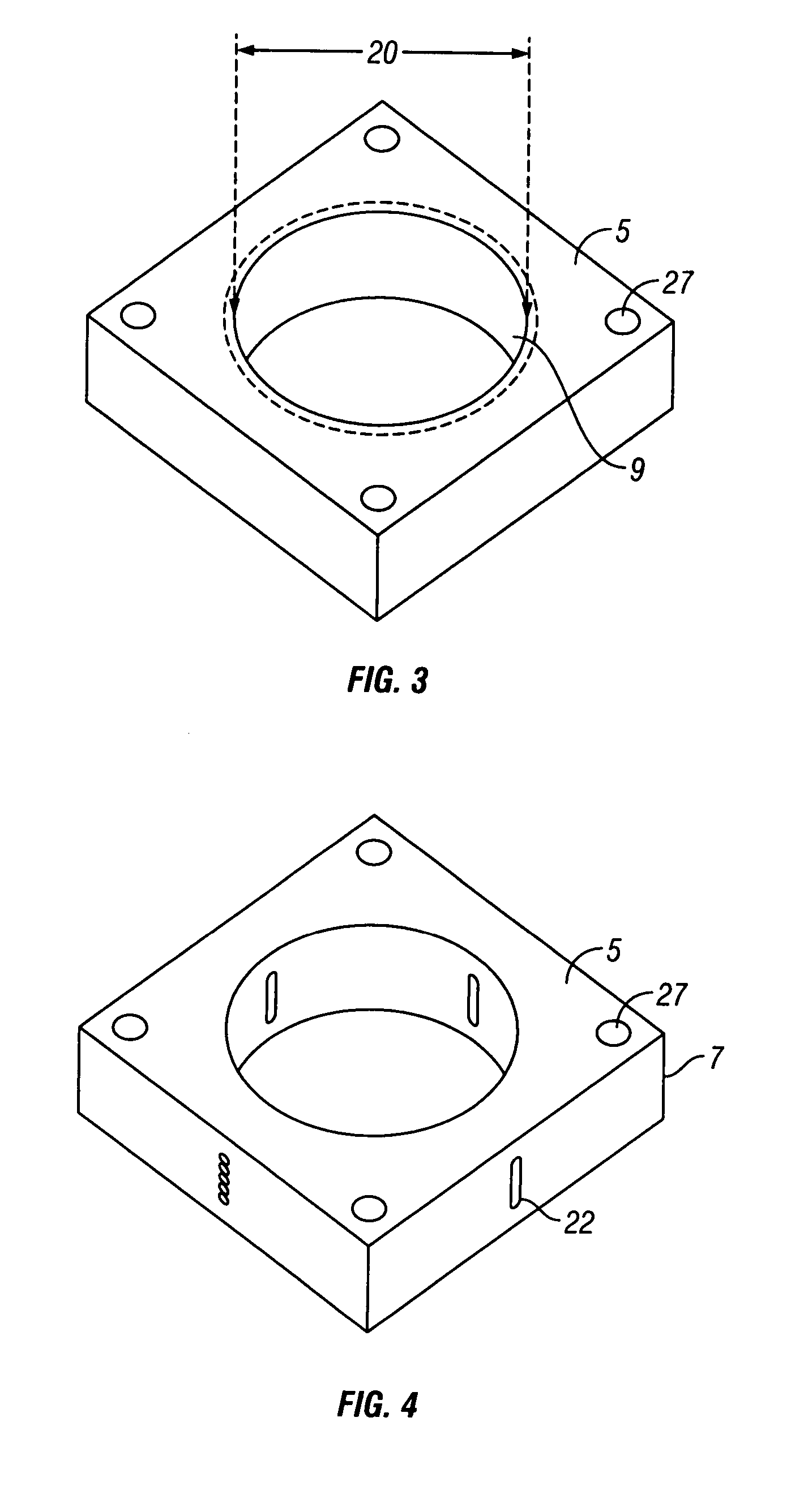
[0024]Referring to FIG. 1, a square throttle body spacer block 5 is shown. The spacer block 5 is preferably made of thermoset resin which absorbs significantly less heat than aluminum. It is preferable to use virgin Teflon® which has a high maximum service temperature of 554° F. The spacer block 5 can range in thickness and height from about ⅜ inches to 2 inches and is preferably one inch thick. The width and length of the preferred embodiment are 3⅛ inches×3⅛ inches. In another embodiment, the block 5 may be a rectangular block, ranging in rectangular profile size from about 3 inches×5 inches to about 5 inches×7 inches. In the preferred embodiment, the one inch thickness of the throttle body spacer block 5 increases the velocity and air force as it passes through the spacers. A meter saw or a table saw (not shown) may be used to ensure that all sides 14 are smooth cut. The edges 6 and corners 7 may be smoothed with a hand file or with 120 grit sandpaper to ensure that they are not ...


PUM

PropertyMeasurementUnit
lengthaaaaaaaaaa
widthaaaaaaaaaa
heightaaaaaaaaaa

Abstract

A throttle body spacer for improving engine performance is provided. It comprises a spacer block with a smooth bore hole, a plurality of air fins, each air fin being connected at one end to the spacer block and the distal end extending to about the center of the bore hole, and a means for mounting the throttle spacer body to hold it in place. In one embodiment the spacer block forming the throttle spacer body is square with a single bore hole in the center. There are four air fins, one mounted from about the middle of each side of the spacer body, that extend to about the center of the hole. The air fins can be made from aluminum and are bent at a forty-five degree angle. In order to accomplish the goal of absorbing less heat, the spacer block forming the throttle body spacer is comprised of thermoset resin. The throttle body spacer has holes located near each corner where fastening elements can be inserted to hold the apparatus in place.

Description

CROSS-REFERENCE TO RELATED APPLICATION[0001]This application claims priority to U.S. Provisional Application No. 60 / 765,155 filed Feb. 3, 2006, entitled “Air Intake Manifold”.BACKGROUND OF THE INVENTION[0002]I. Field of the Invention[0003]The present invention relates generally to the field of apparatus that may increase horsepower, torque, or fuel efficiency in internal combustion engines.[0004]II. Background and Prior Art[0005]There are many different devices available to consumers that are designed to increase power and torque and to improve fuel efficiency in the internal combustion engines of automobiles. One such product is known as a throttle body spacer. Such devices are available from several manufacturers including Airaid®, Jet Performance Products™, and AEM™. They are especially useful with sport utility vehicles, such as Jeep® vehicles, and with any engine having 4.0 L displacement throughout the whole RMP range. The prior art products are machined from aluminum and are ...

Claims


Application Information

Patent Timeline
Patent Type & Authority Patents(United States)
IPC IPC(8): F02M29/00F02B31/00
CPCF02B31/04F02D9/104F02M29/02F02M29/06F02M35/10059F02M35/10262F02M35/10032Y10T29/49908Y02T10/146Y02T10/12
Inventor BOLANOS, ROBERT
Owner GSP POWERSPACER
Why Eureka
Try Eureka