Trailer mounted attenuator with breakaway axle assembly

a technology of axle assembly and attenuator, which is applied in the direction of bumpers, cycle equipment, roads, etc., can solve the problems of trailer not being able to the tendency of the attenuator to be knocked laterally out of the path of the impacting vehicle, etc., to improve the maneuverability of the vehicle and eliminate the two primary deficiencies

Active Publication Date: 2010-04-06
SAFETY BY DESIGN
View PDF16 Cites 10 Cited by
  • Summary
  • Abstract
  • Description
  • Claims
  • Application Information

AI Technical Summary

Benefits of technology

[0004]The basic concept behind the present inventive trailer mounted attenuation (TTMA) is to have the attenuator mounted on a trailer that can be attached to a truck's pintle hook. This inventive concept eliminates the two primary deficiencies of traditional TMAs. Since the center of the present inventive attenuator is supported by the trailer's axle, vertical oscillations in the attenuation system can be controlled, even when the trailer is towed at highway speeds. As a result, the fatigue problem associated with most TMA systems may be avoided completely. Also, there is no need for costly mounting systems that lift the TMA to a vertical position for transport. Further, the trailer improves the maneuverability of the vehicle as compared to a TMA in the down (deployed) position. Since the trailer is attached to the truck's pintle hook, removing the attenuator to allow the truck to be used for other purposes is as simple as unhitching the trailer.
[0005]The primary problem with any trailer attenuation systems is the propensity for the attenuator to be knocked laterally out of the path of the impacting vehicle, such as when a vehicle strikes the end of the trailer at an angle or during offset impacts where only a portion of the front of an impacting vehicle strikes the end of the trailer. This problem can be overcome through the use of engagement elements on the impact end of the trailer. The engagement elements must intrude into the front of an impacting vehicle and prevent it from sliding sideways along the face of the trailer. If the impacting vehicle is restrained from sliding along the trailer's impact face and the attachment between the trailer and the pintle hook is adequate, the trailer cannot be knocked laterally out of the vehicle's path. The engagement elements also allow the trailer to be attached to a conventional pintle hook on the back of a tow trailer. This method for attaching a trailer to a tow vehicle does allow rotation at the point of attachment. However, the mechanical interlock produced by the engagement elements limits the rotation, thus eliminating the need for an advanced hitch design.

Problems solved by technology

The primary problem with any trailer attenuation systems is the propensity for the attenuator to be knocked laterally out of the path of the impacting vehicle, such as when a vehicle strikes the end of the trailer at an angle or during offset impacts where only a portion of the front of an impacting vehicle strikes the end of the trailer.
If the impacting vehicle is restrained from sliding along the trailer's impact face and the attachment between the trailer and the pintle hook is adequate, the trailer cannot be knocked laterally out of the vehicle's path.
However, the mechanical interlock produced by the engagement elements limits the rotation, thus eliminating the need for an advanced hitch design.

Method used


Image

  • Trailer mounted attenuator with breakaway axle assembly
  • Trailer mounted attenuator with breakaway axle assembly
  • Trailer mounted attenuator with breakaway axle assembly

Examples


Embodiment Construction

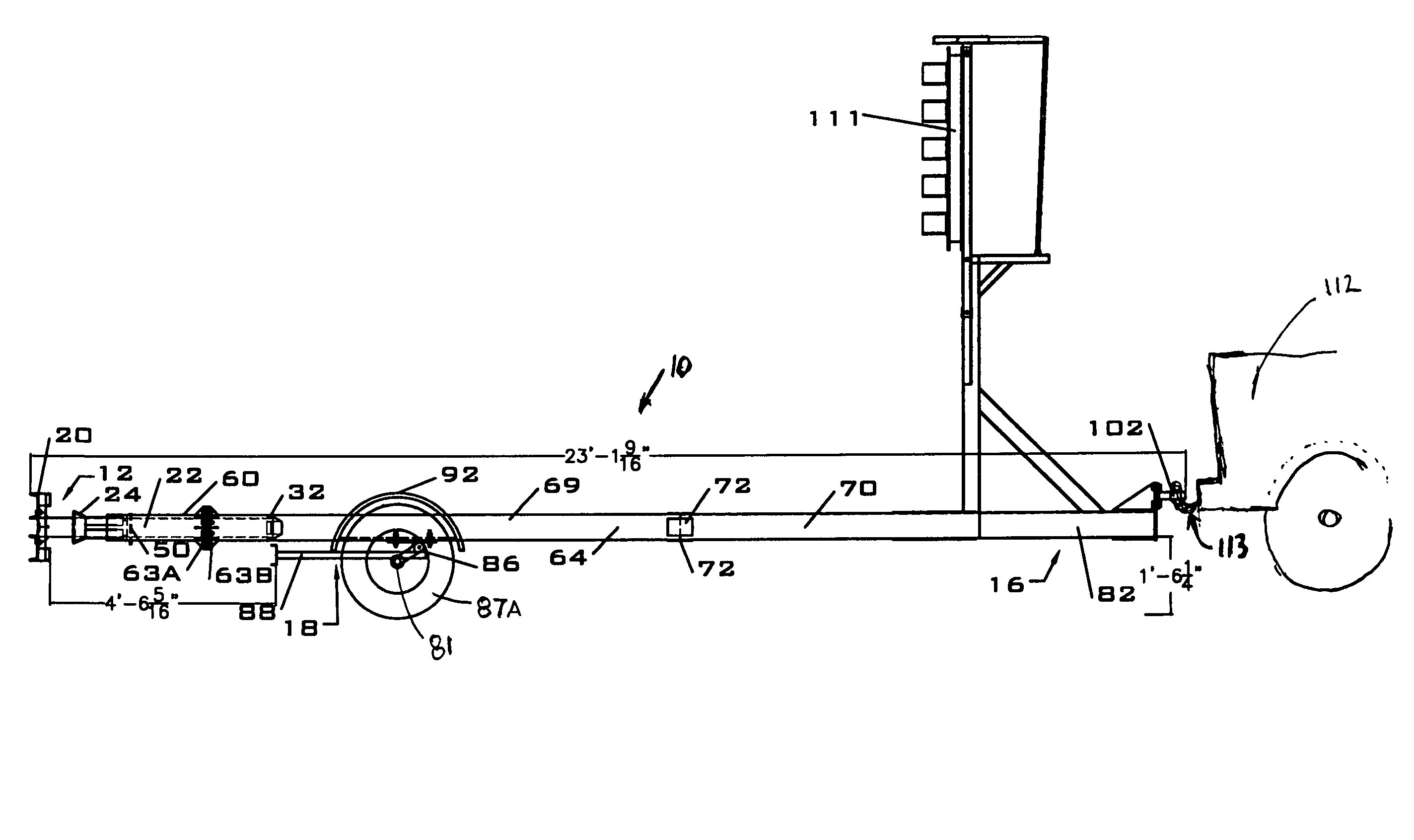
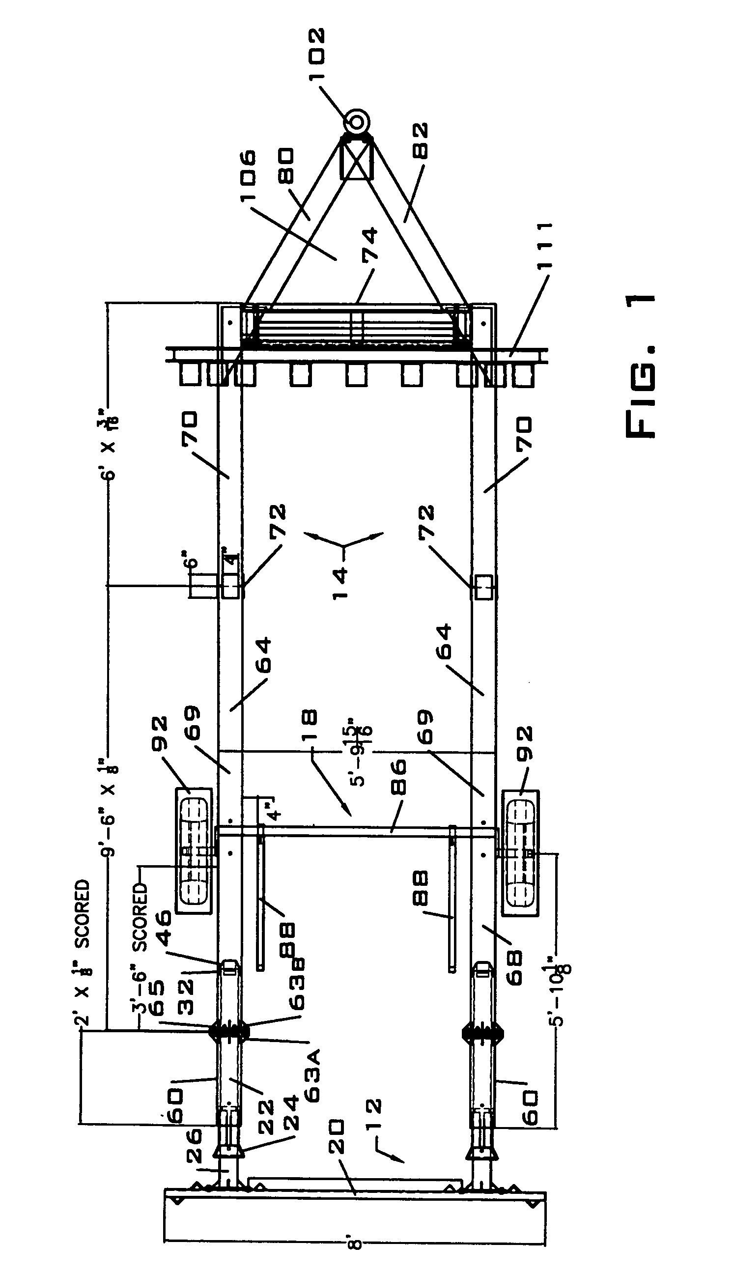
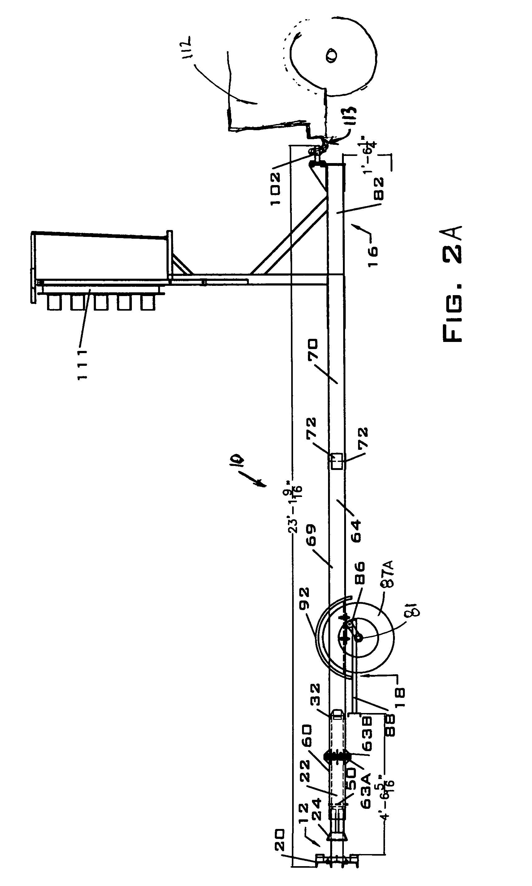
[0038]As seen in FIGS. 1 and 2A and 2B the present inventive trailer mounted attenuator (10) has an impact head assembly (12); a trailer frame (14); a hitch assembly (16); and a breakaway axle assembly (18). FIG. 2A illustrates the journals (81) of the breakaway axle assembly (18) affixed to a conventional wheel set or tire arrangement (87A), and the hitch (102) connected to a towing vehicle (112). FIG. 2B shows the axle assembly (18) affixed to a driven post (87B) and the hitch (102) attached to a fixed object or barrier (104). The post (87B) may be driven into the ground and attached to the assembly (18) anywhere along the length of axle (86) or at the journals (81). Signage (111) may be mounted to the attenuator as required.

[0039]The overall length of the TTMA (10) is 8384 mm (23 ft-1 9 / 16 in.). The maximum width of the trailer assembly is 2438 mm (8 ft.) at the impact head assembly. The height from the ground to the bottom of the trailer frame is 464 mm (18¼ in.). It should be u...


PUM


Abstract

A trailer mounted crash attenuation system has an impact head assembly, a bursting tubular trailer frame member, and a breakaway axle assembly. Upon impact by a vehicle, the head assembly is urged forward bursting the tubular frame of the trailer. As the impact continues, the head assembly contacts an axle accelerator rod which results in the disengagement of the axle, trailer tire, and fenders from the trailer frame member. Impact energy is dissipated by the controlled deceleration of the vehicle as it moves forward through the attenuator system.

Description

BACKGROUND OF THE INVENTION[0001]Highway maintenance vehicles are often parked near roadways or move slowly in or adjacent to high-speed traffic lanes. In these situations, maintenance vehicles pose a serious hazard to the motoring public and the workers. The safety risk associated with these work vehicles is normally minimized through the use of a truck mounted attenuator (TMA).[0002]A TMA is essentially a crash cushion that is cantilevered off of the back of the support truck. The combination of a cantilevered mounting structure and the length of most TMAs produce the potential for large oscillations in the vertical position of the attenuator as the support truck moves down the highway. In other words, the attenuator bounces up and down. These oscillations produce two problems, fatigue loading of TMA components and the potential for the end of the TMA to strike the roadway surface. Support elements and every connection in the structure of a conventional TMA must be strengthened to...

Claims


Application Information

Patent Timeline
Patent Type & Authority Patents(United States)
IPC IPC(8): B62D7/22
CPCB60R19/00B62D21/20B62D21/152B60R2019/005E01F15/148
Inventor REID, JOHN D.ROHDE, JOHN R.MAK, KING K.SICKING, DEAN L.
Owner SAFETY BY DESIGN
Why Eureka
Try Eureka