Connecting piece comprising a gripping element on the outer surface for rotating the connecting piece

a technology of connecting piece and outer surface, which is applied in the direction of screw threaded joints, rod connections, couplings, etc., can solve the problems of leakage points at the threads, the basic structure of the connecting piece to get damaged or the threads to get damaged, and the inability to use too much tightening for

Inactive Publication Date: 2010-04-06
UPONOR INNOVATION AB
View PDF35 Cites 7 Cited by
  • Summary
  • Abstract
  • Description
  • Claims
  • Application Information

AI Technical Summary

Benefits of technology

[0013]The idea of one embodiment is that the gripping element comprises at least two straight portions, i.e. gripping surfaces, on opposite sides of the connecting piece, being intended for a tool, such as an adjustable wrench, a set wrench, pipe tongs or the like tool. Thus, the gripping element can be arranged to give way, for instance in such a way that the portions between adjacent gripping surfaces are formed rounded. In this case, it is possible to grip the connecting piece tightly with a tool, and when the tool turns around relative to the connecting piece, the outer surface of the connecting piece will not get substantially damaged. The gripping element can be formed to comprise, for example, six straight portions, like a nut. Further, the gripping element can be formed of ribs that are in the direction of the periphery and arranged on the outer surface of the connecting piece. Ribs on the outer surfaces have the advantage that when the connecting piece is injection-moulded, the plastic part of the connecting piece cools relatively quickly and no stresses are generated inside the plastic piece during the casting. Further, the ribs strengthen the wall structure, whereby it is not necessary to make the wall of the plastic piece body very thick. Since the wall needs not be thick, substantially no thick points are formed in the plastic piece during casting which could generate suction points in the plastic material during casting or cavities in the finished piece. The outer surface of the metal insert in the connecting piece may be provided, in the direction of the periphery of the insert, with ribs or grooves which improve the attachment of the metal insert and the plastic part to each other. Thus, the ribs outside the connecting piece can be arranged at the same point as the ribs of the metal insert. Thus, the thickness of the plastic part wall of the connecting piece remains substantially uniform over the whole portion of the connecting piece, which, for its part, decreases stresses generated inside the plastic piece during casting, because the plastic cools evenly as the wall is of substantially uniform thickness over the whole area.

Problems solved by technology

Thus, upon making the threaded connection, it is not possible to use too great a tightening force.
Using too great a tightening force would result in the basic structure of the connecting piece to get damaged or the threads to get damaged, which, in turn, would cause a leak point at the threads, for example.

Method used


Image

  • Connecting piece comprising a gripping element on the outer surface for rotating the connecting piece
  • Connecting piece comprising a gripping element on the outer surface for rotating the connecting piece

Examples


Embodiment Construction

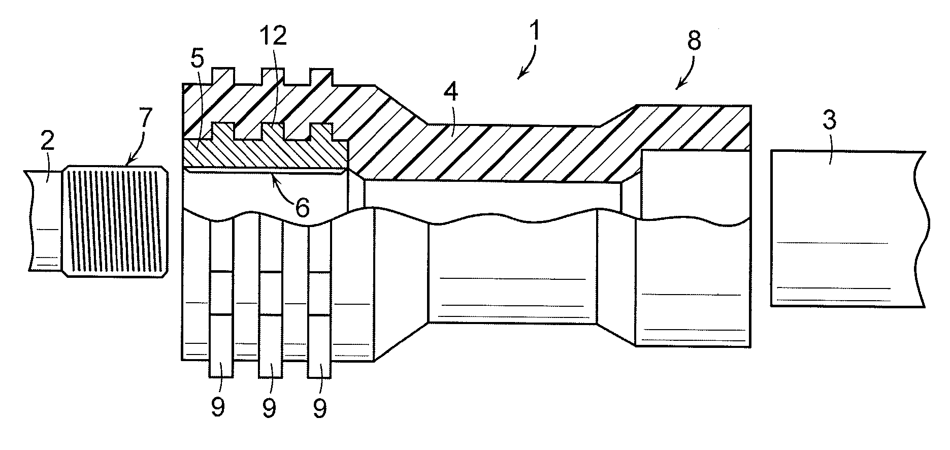
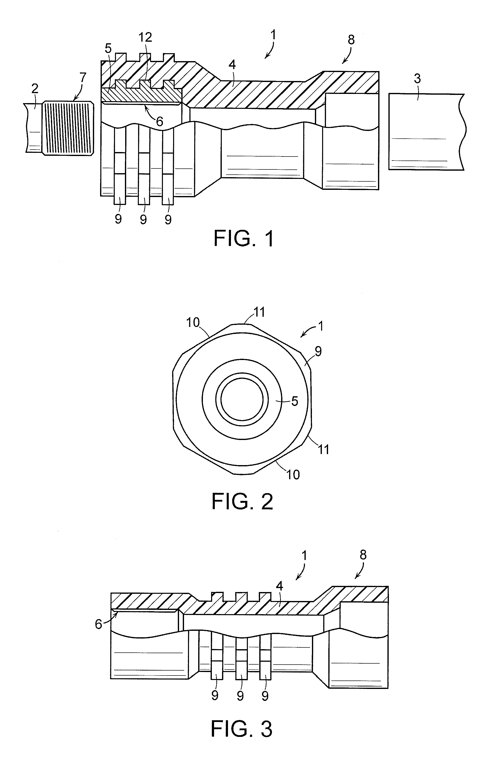
[0019]FIG. 1 shows a connecting piece 1. The connecting piece 1 is used between a first element 2 and a second element 3 to connect them. The first element 2 may be, for instance, a metal pipe or a fitting, such as a tap or the like, and the second element 3 may be a plastic pipe, for instance. The connecting piece 1 may be straight, as illustrated in FIG. 1, or it may be a bend, for example. Further, the connecting piece 1 may be a T branch, for example, in which case three elements are connected to each other with it. Hence, the appearance and the object of use of the connecting piece 1 may vary even to a large extent.

[0020]The body 4 of the connecting piece 1 is preferably of plastic, such as polyethylene PE, polypropylene PP, cross-linked polyethylene PEX, polyamide PA, polysulphone PSU or polyphenyl sulphone PPSU. A first end of the body 4 of the connecting piece 1 is provided with a metal insert 5. The metal insert 5 may be, for instance, of brass or other metal suitable for t...


PUM

PropertyMeasurementUnit
circumferential lengthaaaaaaaaaa
plasticaaaaaaaaaa
structureaaaaaaaaaa

Abstract

A first element is connected to a first end of a connecting piece and a second element is connected to a second end of the connecting piece. At least one end of the connecting piece is provided with a thread, whereby the connecting piece is connectable to a pipe or fitting with a threaded connection. The connecting piece is made of plastic in such a way that a metal insert provided with a thread is arranged at at least one end of the plastic body of the connecting piece, or the connecting piece is made substantially completely of thermoplast in such a way that the thermoplastic body is provided with a thread. The outer surface of the connecting piece is provided with a gripping member. The gripping member is formed and dimensioned such that it gives way earlier than the connecting member thread and / or basic structure.

Description

FIELD OF THE INVENTION[0001]The invention relates to a connecting piece, intended for connecting at least two elements, whereby a first element is connected to a first end of the connecting piece and a second element is connected to a second end of the connecting piece, the body of the connecting piece being mainly of plastic and a metal insert provided with a thread being arranged at at least one end of the connecting piece, whereby at least one element is connectable to the connecting piece with threaded connection and there is at least one gripping element on the outer surface of the connecting piece for rotating the connecting piece or keeping it still upon making the threaded connection.[0002]Further, the invention relates to a connecting piece, intended for connecting at least two elements, whereby a first element is connected to a first end of the connecting piece and a second element is connected to a second end of the connecting piece, the body of the connecting piece being...

Claims


Application Information

Patent Timeline
Patent Type & Authority Patents(United States)
IPC IPC(8): F16L37/24F16B7/18
CPCF16B7/182F16L47/24
Inventor SMAHL, JARMO
Owner UPONOR INNOVATION AB
Why Eureka
Try Eureka