Fiber optic connector, active contact inserts therefor, and associated methods

a fiber optic connector and active contact technology, applied in the field of connectors, can solve the problems of increasing the cost, weight and complexity of the electronic system, adding to the overall volume of the system, and affecting the quality of the optical connector, and achieve the effect of being ready for manufacture and assembly

Active Publication Date: 2010-04-06
MOOG INC
View PDF27 Cites 33 Cited by
  • Summary
  • Abstract
  • Description
  • Claims
  • Application Information

AI Technical Summary

Benefits of technology

[0012]In view of the foregoing background, it is therefore an object of the present invention to provide an active fiber optic connector insert that may be mechanically robust and thereby reliable yet still readily manufactured and assembled.
[0014]The fiber optic connector insert may further include an opto-electronic (O / E) converter comprising a second base and at least one second electrically conductive pin extending outwardly therefrom. The second electrically conductive pin may be further coupled to the circuit board adjacent the second end thereof. In other words, the circuit board may be straddle mounted on the first and second electrically conductive pins carried by the first and second bases, respectively. Advantageously, the fiber optic connector insert may be readily manufactured and assembled, and the fiber optic connector insert may be mechanically robust, thereby resistant to harsh environments. The fiber optic connector insert may further comprise a retention shoulder on the housing for mounting the fiber optic connector insert within the passageway of the connector body, for example.
[0020]At least the housing and the second base may comprise electrically conductive material, for example. Advantageously, the electrically conductive material may provide electromagnetic shielding. The fiber optic connector insert may further comprise a dielectric potting material surrounding the circuit board and filling the housing. The dielectric potting material may provide both mechanical protection to the circuitry carried by the circuit board.

Problems solved by technology

When routing each optical fiber from the connector to an appropriate O / E converter within the housing, several difficulties may occur.
The use of an optical fiber backplane within the housing may add to the cost, weight and complexity of the electronic system, as well as to the overall volume of the system.
This added weight may be particularly problematic for connectors which are used in aircraft applications.

Method used


Image

  • Fiber optic connector, active contact inserts therefor, and associated methods
  • Fiber optic connector, active contact inserts therefor, and associated methods
  • Fiber optic connector, active contact inserts therefor, and associated methods

Examples


Embodiment Construction

[0026]The present invention will now be described more fully hereinafter with reference to the accompanying drawings, in which preferred embodiments of the invention are shown. This invention may, however, be embodied in many different forms and should not be construed as limited to the embodiments set forth herein. Rather, these embodiments are provided so that this disclosure will be thorough and complete, and will fully convey the scope of the invention to those skilled in the art. Like numbers refer to like elements throughout.

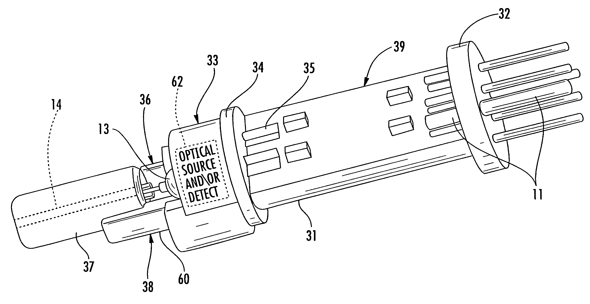
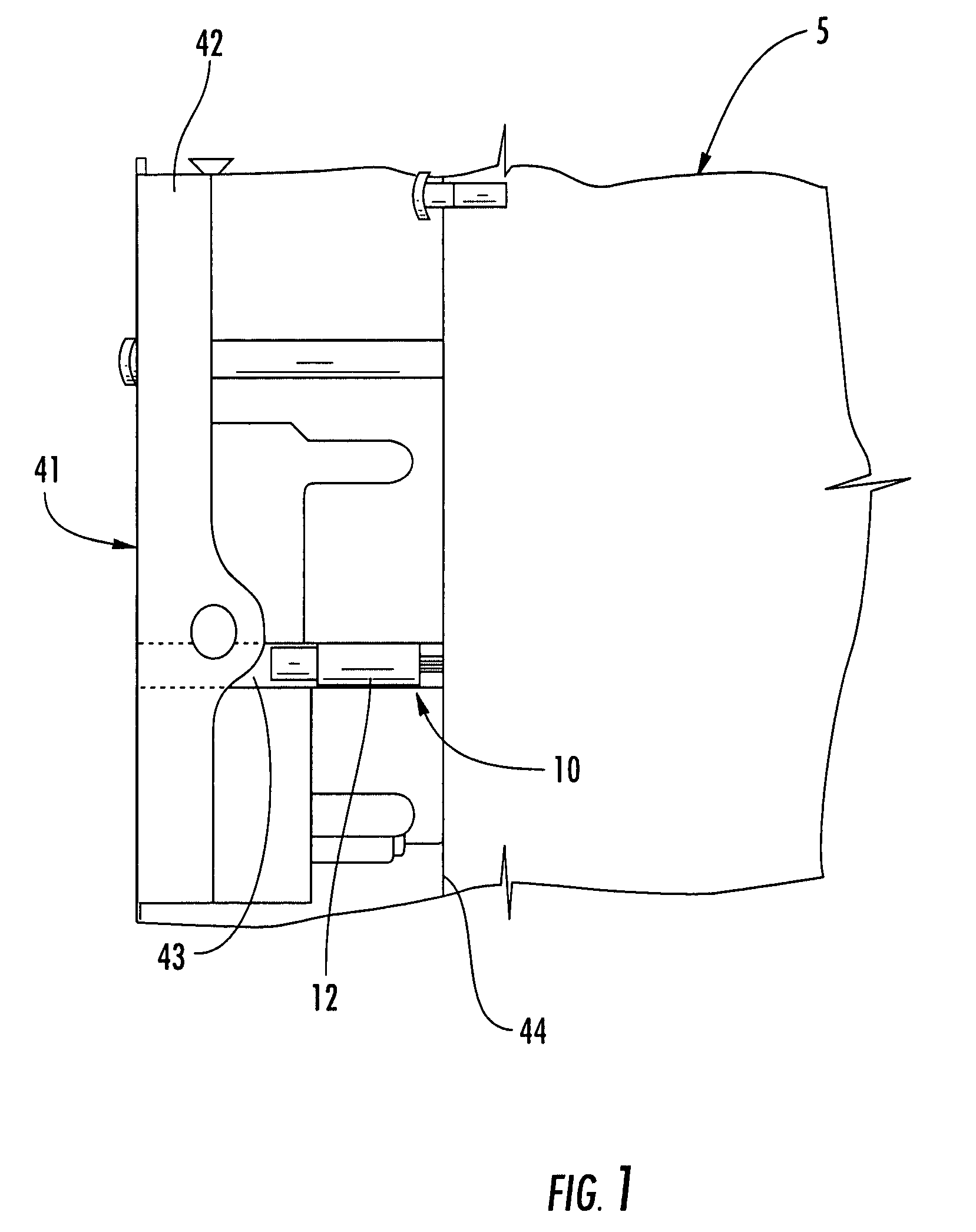
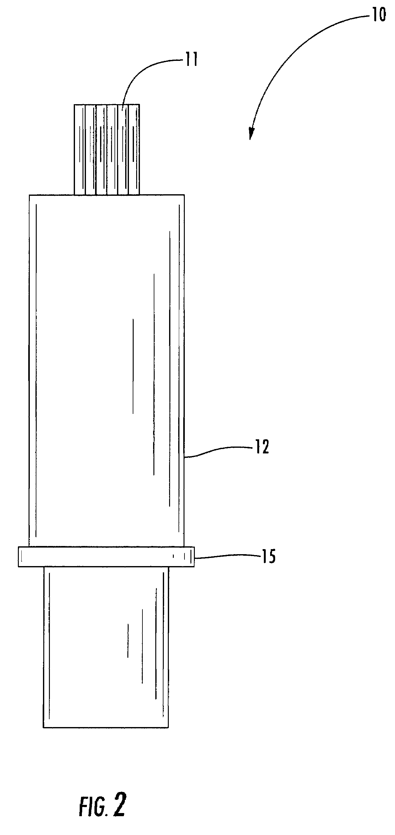
[0027]Referring initially to FIG. 1, a fiber optic connector 41 installed in an electronic device 5 is now described. The connector 41 includes a connector body 42 having a plurality of passageways 43 therein for mounting respective fiber optic connector inserts 10, only one of which is shown for clarity of explanation. The connector 41 illustratively comprises an ARINC Series 600 connector, for example, but as will be appreciated by those skilled in the a...


PUM


Abstract

A fiber optic connector insert for a connector may include a housing to be received within a passageway of a connector body, a circuit board extending longitudinally within the housing and having opposing first and second ends, and a first base and first electrically conductive pins carried thereby. The first electrically conductive pins may be coupled to the circuit board adjacent the first end thereof. The fiber optic connector insert may also include an opto-electronic (O / E) converter having a second base and second electrically conductive pins extending outwardly therefrom. The second electrically conductive pins may be coupled to the circuit board adjacent the second end thereof.

Description

FIELD OF THE INVENTION[0001]The present invention relates to the field of connectors, and, more particularly, to optical connectors and related methods.BACKGROUND OF THE INVENTION[0002]Fiber optic cabling is used in various types of air, space, land, and sea-based platforms to provide high-speed data communications for on-board electronic systems, such as radar and mission control computer systems. In a typical fiber optic connector, one portion of the connector is coupled to the housing of the electronic system and extends rearwardly therefrom. A passive mating insert, for example, a Series 801 (1.25 mm / 2.5 mm diameter) fiber optic ferrule from the Aeronautical Radio, Incorporated of Annapolis, Md. or an Military Standard 29504 (1.6 mm diameter) fiber optic ferrule (passive mating insert), may be removably positioned into each passageway of the body of the fiber optic connector. The connector body may comprise, for example, a standard Series 600 connector from Aeronautical Radio, I...

Claims


Application Information

Patent Timeline
Patent Type & Authority Patents(United States)
IPC IPC(8): G02B6/36H04B10/00
CPCG02B6/4292G02B6/4246
Inventor SCHARF, ROBERT MARCLORD, RANDAL BRUCE
Owner MOOG INC
Why Eureka
Try Eureka