Electron beam systems

a technology of electron beam and beam beam, applied in the direction of electrode and associated part arrangement, electric variable regulation, amplifier, etc., can solve the problems of high data rate that cannot be implemented previously, and the cost of known analog amplifiers, which allow higher driving frequencies, is too high, and achieves the effect of precise driving of inductance or deflection coils

Active Publication Date: 2010-04-06
GLOBAL BEAM TECH
View PDF14 Cites 2 Cited by
  • Summary
  • Abstract
  • Description
  • Claims
  • Application Information

AI Technical Summary

Benefits of technology

[0006]The present teachings provide, e.g., improved techniques for driving an inductance, such as a deflection coil of an electron beam gun, and improved images generated from back-scattered electrons, which are possible with a high-speed and precise driving of the inductance or deflection coil.
[0014]By using a stored processing- and scanning-pattern, which is read out at a high data rate, the generation of an image of the to-be-processed work piece is possible. For example, the electron source can “quasi”-simultaneously process the work piece and can be guided in intervals over the to-be-scanned surface areas of the work piece currently being processed while retaining the welding capillary or capillaries, respectively, in these intervals. A color image can be generated from the registered back-scattered electrons.
[0015]Thus, in one advantageous embodiment of the present teachings, an electron beam system that is equipped with a high-speed amplifier, which uses the current-adding array of one the types provided herein, can be controlled very quickly and effectively using the data rates made available by present-day data processing technology. Naturally, improvements in processing technologies and speeds in the future, which are fully contemplated by the present teachings, will only make the present technology more advantageous.

Problems solved by technology

However, with the previously achievable 100 kHz as the control frequency for deflection coils, such a high data rate could not previously be implemented at a correspondingly high deflection rate for deflecting an electron beam of an electron beam gun.
Moreover, known analog amplifiers, which allow higher driving frequencies, would be too expensive.

Method used


Image

  • Electron beam systems
  • Electron beam systems
  • Electron beam systems

Examples


Embodiment Construction

[0023]As will be described in further detail below, the present teachings generally comprise at least the following subject matters:

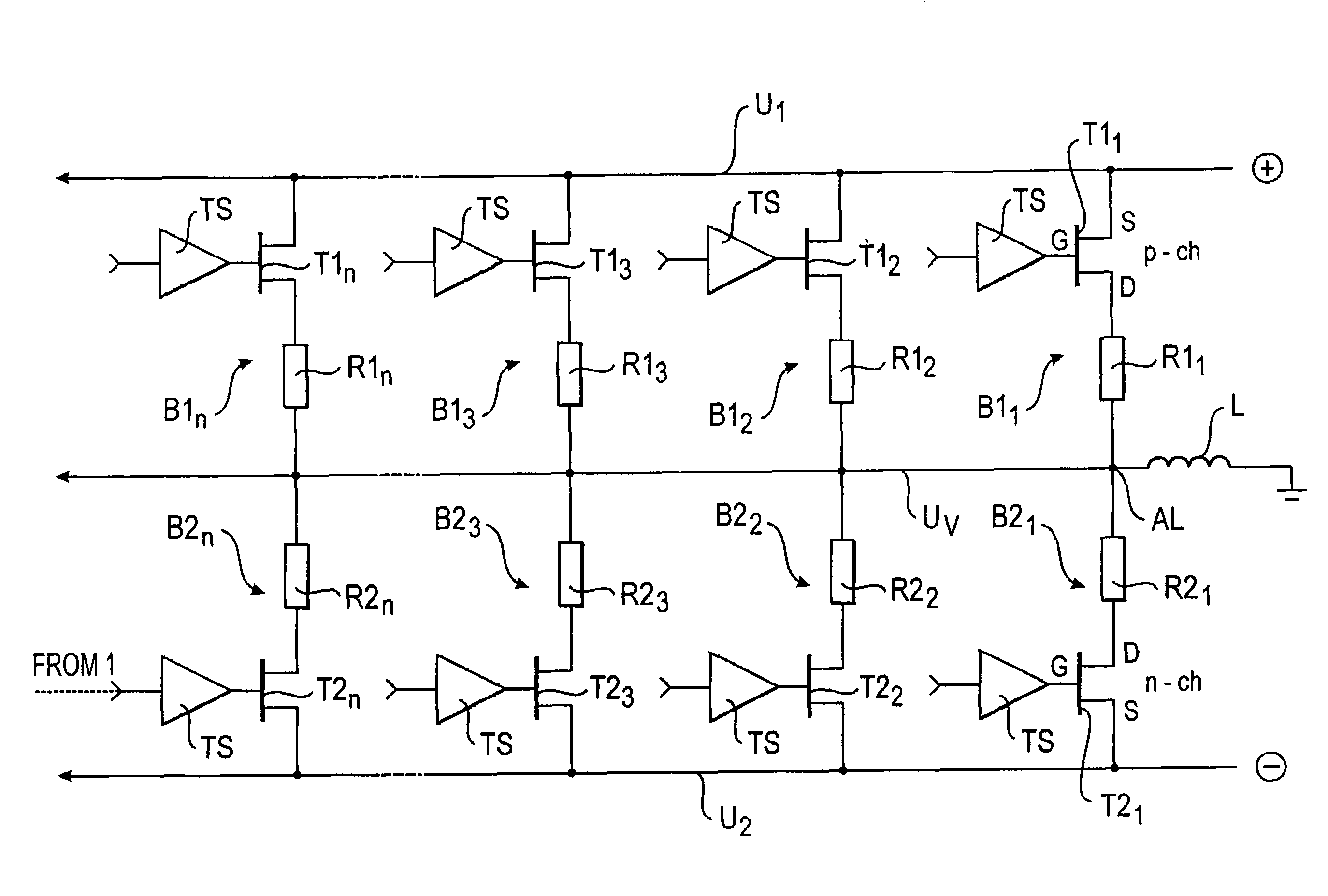
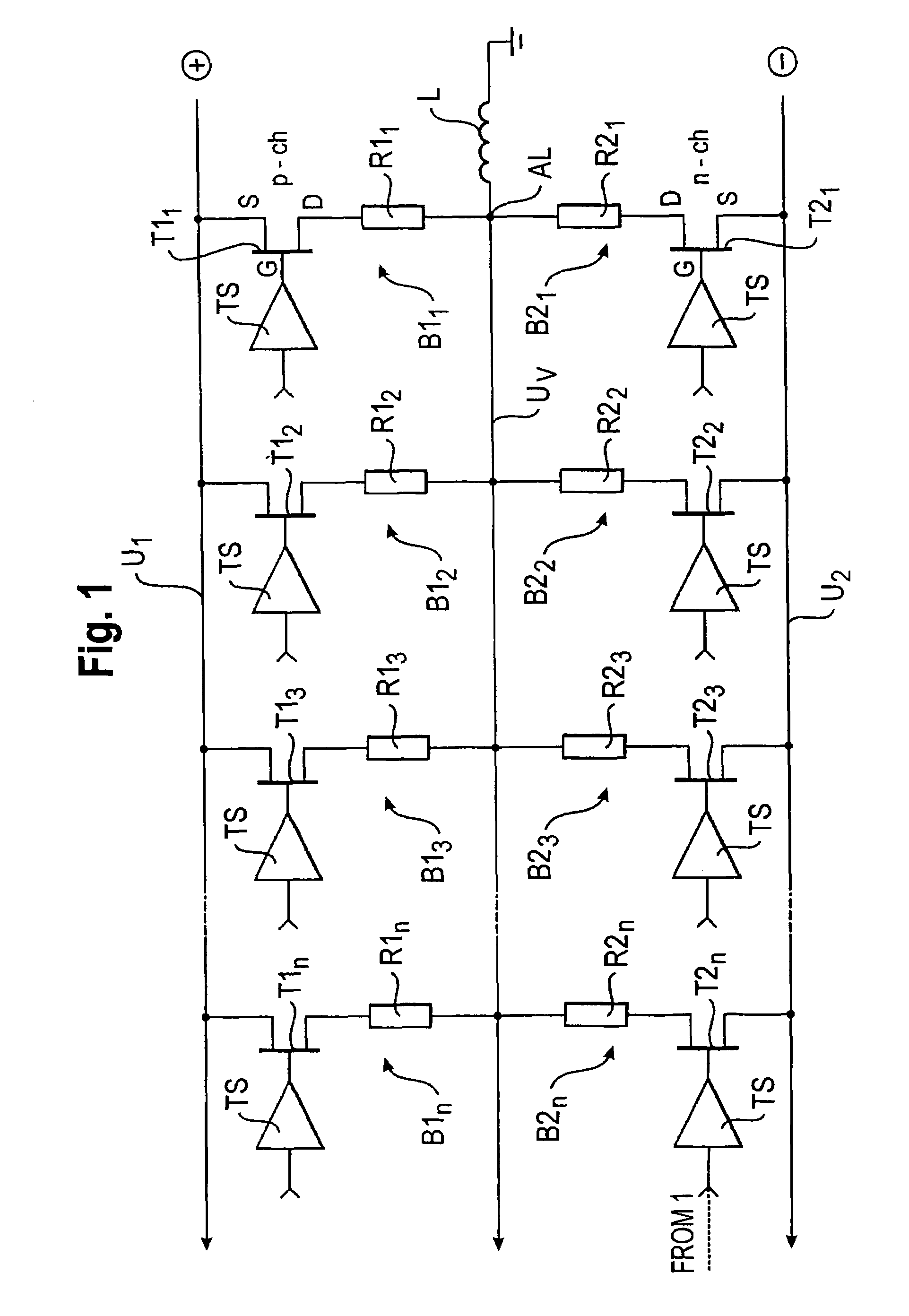
[0024]1. An amplifier for high-speed driving of an inductive element, preferably a deflection coil of an electron beam gun, including a current-adding array preferably having a first voltage node (U1) adapted to be connected with a voltage-stabilized power supply and a second voltage node (UV) adapted to be connected with a first output (AL) for supplying power to the inductive element (L). A plurality of first switchable bridges (B11, B12, B13, . . . , B1k) preferably each have at least one resistor (R11, R12, R13, . . . , R1k) with a resistance value that is switchable in parallel between the first voltage node (U1) and the second voltage node (UV). The resistance values are preferably selected so that a first resistor (R11) has a first resistance value WR11=Rmin, a second resistor (R12) has a second resistance value WR12≧WR11 and the n-th resistor ha...


PUM

PropertyMeasurementUnit
currentaaaaaaaaaa
rated currentaaaaaaaaaa
frequencyaaaaaaaaaa

Abstract

A high-power amplifier having a current-adding array is provided for high-speed driving of an inductive element, e.g., a deflection coil of an electron beam gun. The amplifier includes a first voltage node (U1) and a second voltage node (UV), at least one of which is connected to a regulated power supply, and a plurality of first switchable bridges (B11, B12, B13, . . . , B1k) connected in parallel between the first and second voltage nodes. Each switchable bridge includes at least one resistor (R11, R12, R13, . . . , R1k) with a resistance value that is selected so that a first resistor (R11) has a first resistance value WR11 equal to Rmin, a second resistor (R12) has a second resistance value WR12 greater than or equal to WR11 and an n-th resistor has an n-th resistance value WR1n greater than or equal to WR1n−1.

Description

CROSS-REFERENCE[0001]This application claims priority to German patent application no. 10 2006 035 793.0 filed 28 Jul. 2006, the contents of which are incorporated herein as if fully set forth herein.TECHNICAL FIELD[0002]The present teachings generally relate to electron beam systems for material processing, such as e.g., welding, cutting, hardening or the like. More particularly, the present teachings relate to an amplifier having a current-adding array for high-speed driving of an inductance or inductive element, e.g., a deflecting coil of an electron beam gun. Further, the present teachings also relate to an image generating device for generating an image of a work piece processed by an electron beam system before and / or during the material processing.BACKGROUND ART[0003]In the state of the art of material processing using electron beams, it is known to drive the deflection coil of the electron beam gun using analog amplifiers that have a high-level signal control frequency of up...

Claims


Application Information

Patent Timeline
Patent Type & Authority Patents(United States)
IPC IPC(8): H05B39/04
CPCB23K15/0026B23K15/0046B23K15/02H01J37/24H03F3/217H01J37/315H01J37/31H01J2237/2485H01J2237/30483
Inventor ZOSEL, KARSTEN
Owner GLOBAL BEAM TECH
Why Eureka
Try Eureka