Bearing assembly having rotation sensor and mounting structure to support sensor cap and connector

a technology of rotating sensors and mounting structures, which is applied in the direction of mechanical equipment, instruments, transportation and packaging, etc., can solve problems such as difficult assembly, and achieve the effects of reducing assembly difficulty, simplifying structure, and preventing deterioration

Inactive Publication Date: 2010-04-06
NTN CORP
View PDF23 Cites 13 Cited by
  • Summary
  • Abstract
  • Description
  • Claims
  • Application Information

AI Technical Summary

Benefits of technology

[0014]An object of the present invention is to provide a rotation sensor incorporated bearing assembly, capable of outputting a signal for a substantial period of time accurately and stably.

Problems solved by technology

Because of this, depending on the diametric dimension of the outer periphery of the sensor connector 42 and / or the diametric dimension of the inner periphery of the sensor cap 32, the press-fitting allowance varies considerably and, as a result, a press-fitting load changes, resulting in difficulty in assemblage.

Method used


Image

  • Bearing assembly having rotation sensor and mounting structure to support sensor cap and connector
  • Bearing assembly having rotation sensor and mounting structure to support sensor cap and connector
  • Bearing assembly having rotation sensor and mounting structure to support sensor cap and connector

Examples


first embodiment

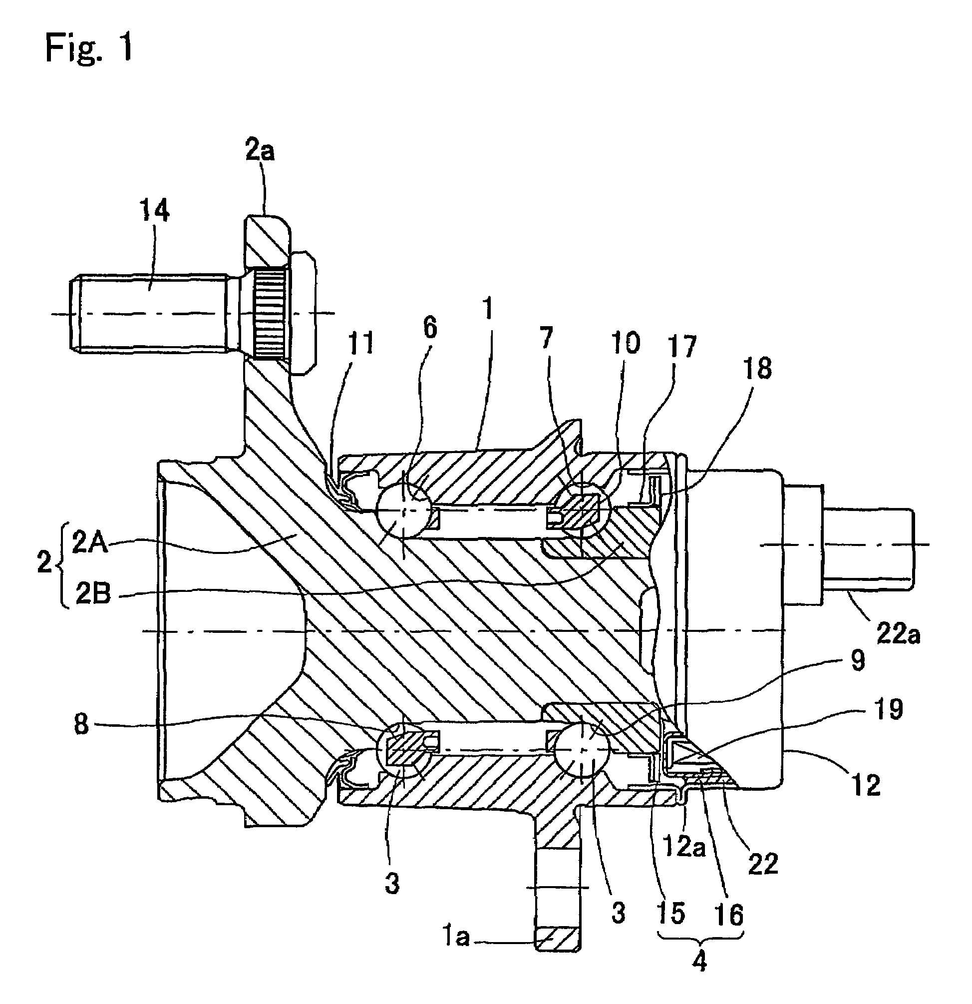
[0061]It is to be noted that although the first embodiment has been described as applied to the wheel support bearing assembly, the present invention can be equally applied to a rolling bearing in general such as a deep groove ball bearing.

[0062]Hereinafter, a second preferred embodiment of the present invention will be described with reference to the accompanying drawings.

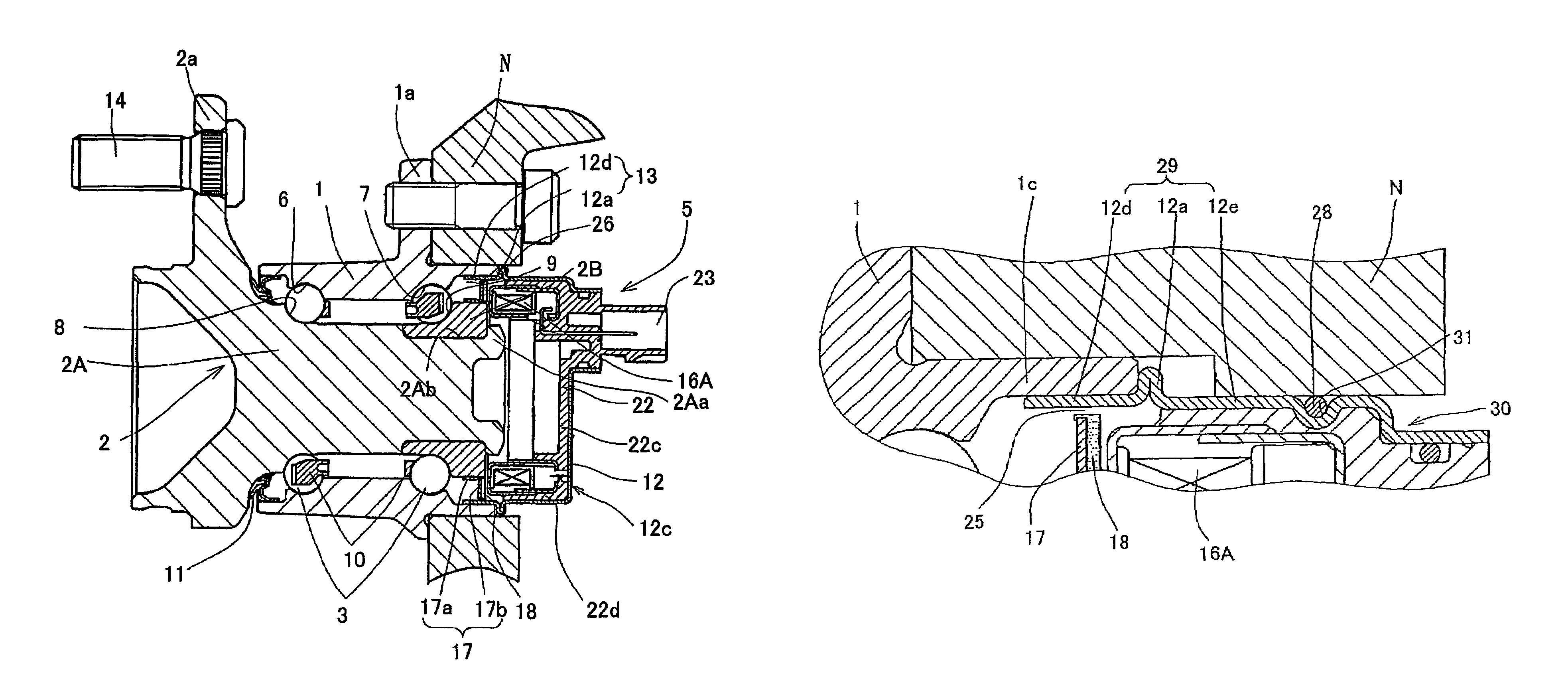
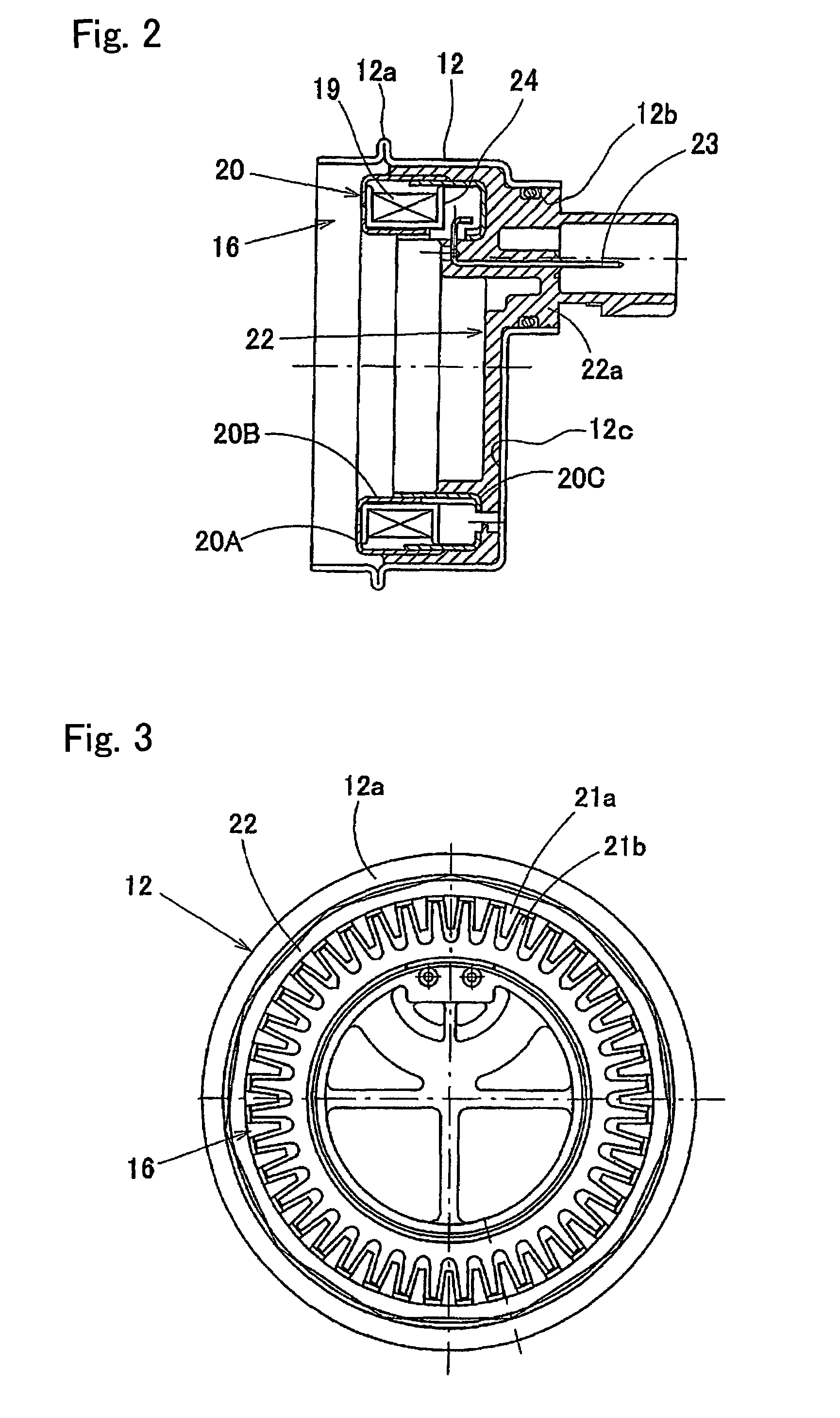
[0063]FIG. 6 is a longitudinal sectional view of the rotation sensor incorporated bearing assembly according to the second preferred embodiment of the present invention, FIG. 7 is an enlarged view of an important portion of FIG. 6, and FIG. 8 is an enlarged view showing a modification of FIG. 7.

[0064]This rotation sensor incorporated bearing assembly includes an inner member 2, an outer member 1 and double rows of rolling elements (balls) 3 and 3 accommodated between those members 2 and 1. The inner member 2 is made up of a hub axle 2A and an inner race 2B which is a member separate from the hub axle 2A and mounte...

second embodiment

[0065]The hub axle 2A has one end formed with a wheel mounting flange 2a, to which an automotive vehicle wheel (not shown) is fitted by means of hub bolts 14 circumferentially equidistantly implanted in this wheel mounting flange 2a for the securement of the vehicle wheel. The hub axle 2A has an outer periphery formed with an inner raceway surface 8 and a reduced diameter stepped portion 2Ab extending axially from this inner raceway surface 8. The inner race 2B formed with an inner raceway surface 9 is press-fitted onto this reduced diameter stepped portion 2Ab and is fixed axially to the hub axle 2A by means of a crimped portion 2Aa formed by plastically deforming one end of the reduced diameter stepped portion 2Ab in a radially outward direction. In the second embodiment, owing to the use of such a self-retaining structure in which the inner race 2B is firmly retained by the crimped portion 2Aa, there is no need to control the amount of a preload by firmly fastening the inner race...


PUM


Abstract

A wheel support bearing assembly includes an outer member inserted in a knuckle, an inner member made up of a hub axle, double rows of rolling elements, and a cover closing an opening of one end of the outer member. The cover includes a sensor connector and a sensor cap. A pulsar ring is mounted on the inner race and a rotation sensor is opposed to the pulsar ring and embedded in the sensor connector. The cover extends over an outer surface of the sensor connector. The cover has a cylindrical portion mounted in an inner peripheral surface of one end of the outer member, which end forms a pilot portion for the knuckle. The cylindrical portion of the cover has an outer periphery provided with an annular elastic member held in contact with an inner peripheral surface of the knuckle.

Description

CROSS REFERENCE TO RELATED APPLICATION[0001]This application is base on International Application PCT / JP2005 / 016321 filed Sep. 6, 2005 and Japanese Application Nos. 2004-268211 filed Sep. 15, 2004 and 2004-325197 filed Nov. 9, 2004, the disclosures of which are hereby incorporated herein by reference.FIELD OF THE INVENTION[0002]The present invention relates to a bearing assembly having a rotation sensor incorporated therein, which assembly is of a type that can be used as, for example, a wheel support bearing for rotatably supporting wheels relative to a suspension system of, for example, an automotive vehicle equipped with an anti-lock brake system or a bearing for any other machines and equipments and, more particularly, to a mounting structure in the bearing assembly for supporting a sensor cap and a sensor connector.BACKGROUND ART[0003]The anti-lock brake system (ABS) is designed to detect the occurrence of tires being locked during run on a low friction road surface or at the t...

Claims


Application Information

Patent Timeline
Patent Type & Authority Patents(United States)
IPC IPC(8): G01P3/48F16C19/08
CPCF16C33/723F16C41/007G01D11/245G01P3/443F16C33/768G01P1/026F16C2326/02F16C19/186
Inventor YAMAMOTO, KAZUNARIOHTSUKI, HISASHI
Owner NTN CORP
Why Eureka
Try Eureka