Common mode choke coil

a choke coil and common-mode technology, applied in the direction of transformer/inductance details, basic electric elements, inductances, etc., can solve the problems of return loss, reflected and attenuated signals transmitted through the transmission channel, and high-frequency signals (200 mhz or higher) or high-speed pulse signals. , to achieve the effect of enhancing the insulation resistance of voltage and reducing the effect of the third and fourth coil conductors

Active Publication Date: 2010-04-06
TDK CORPARATION
View PDF14 Cites 20 Cited by
  • Summary
  • Abstract
  • Description
  • Claims
  • Application Information

AI Technical Summary

Benefits of technology

[0012]According to the present invention, since the third coil conductor and the fourth coil conductor have the same shape and are in a linear symmetrical relationship, fluctuation in the inductance of the third coil conductor and the fourth coil conductor can be reduced, and reduction of the characteristic impedance can be reliably suppressed. In the present invention, the state of being substantially magnetically coupled is a state in which the coupling coefficient is 0.9 or higher. The state of being substantially not magnetically coupled is a state in which the coupling coefficient is 0.1 or lower.
[0020]In the present invention, a directional mark formed on a side surface of the common mode choke coil main body is preferably furthermore provided. In this case, it is furthermore preferred that the directional mark be a conductor pattern that is provided in the same layer as any of the first through fourth coil conductors and the first and second contact conductors. The effects of the third and fourth coil conductors may be slightly reduced when the common mode choke coil of the present invention is packaged in a wrong orientation, but providing such a directional mark makes it possible to clearly define the orientation of the common mode choke coil body and to prevent the common mode choke coil from being packaged in a wrong orientation. When the directional mark is formed together with the first through fourth coil conductors, or together with the first and second contact conductors, the directional mark can be formed without the use of specialized processes such as printing or laser processing.

Problems solved by technology

Although a differential transmission system has the characteristics of strong external noise suppression and no generation of noise, common mode noise is actually generated by slight imbalances of the two signals, and such noise is emitted from interface cables and the like.
In HDMI and other high-speed interfaces, the structure of the ICs as such has become vulnerable to ESD (Electrostatic Discharge) as speed has been increased.
However, when a capacitive element is inserted as an ESD protection component in a transmission channel, drawbacks occur in that the signals transmitted through the transmission channel, particularly high-frequency signals (200 MHz or higher) or high-speed pulse signals, are reflected and attenuated.
When there is a portion of the transmission channel in which the impedance is mismatched, the high-frequency component of the signal causes reflection in the impedance-mismatched portion, and return loss therefore occurs.
As a result, the signal is significantly attenuated.
The reflection also sometimes causes unwanted radiation in the transmission channel, which causes noise.
However, merely adding a characteristic impedance adjustment coil to the common mode choke coil is inadequate, and there is a need for a characteristic impedance adjustment coil having satisfactory characteristics in which there is minimal fluctuation in the inductor values of two characteristic impedance adjustment coils, and in which magnetic coupling between inductors is adequately suppressed.

Method used


Image

  • Common mode choke coil
  • Common mode choke coil
  • Common mode choke coil

Examples


first embodiment

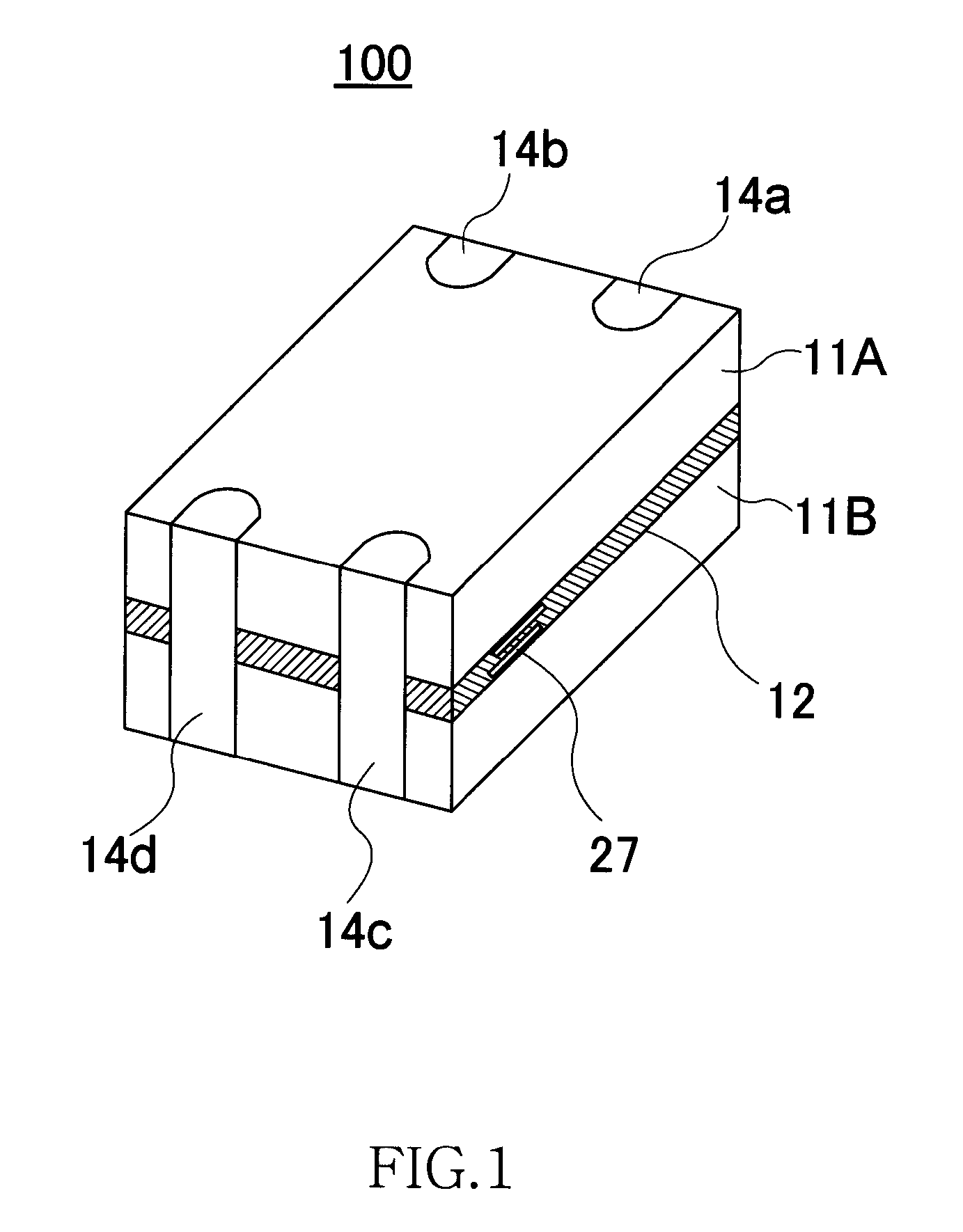
[0033]FIG. 1 is a schematic perspective view showing a structure of a common mode choke coil 100 according to the present invention.

[0034]As shown in FIG. 1, the common mode choke coil 100 is a thin-film type coil, and is provided with first and second magnetic substrates (magnet layers) 11A, 11B and a layer assembly 12 interposed between the first magnetic substrate 11A and the second magnetic substrate 11B. Terminal electrodes 14a through 14d are formed in the external peripheral surface of a layered body composed of the first magnetic substrate 11A, the layer assembly 12, and the second magnetic substrate 11B. A directional mark 27 described in detail hereinafter is also formed on the side surface of the common mode choke coil 100.

[0035]The first and second magnetic substrates 11A, 11B physically protect the layer assembly 12 and serves as a closed magnetic circuit of the common mode choke coil. Sintered ferrite, composite ferrite (a resin containing powdered ferrite), or the lik...

second embodiment

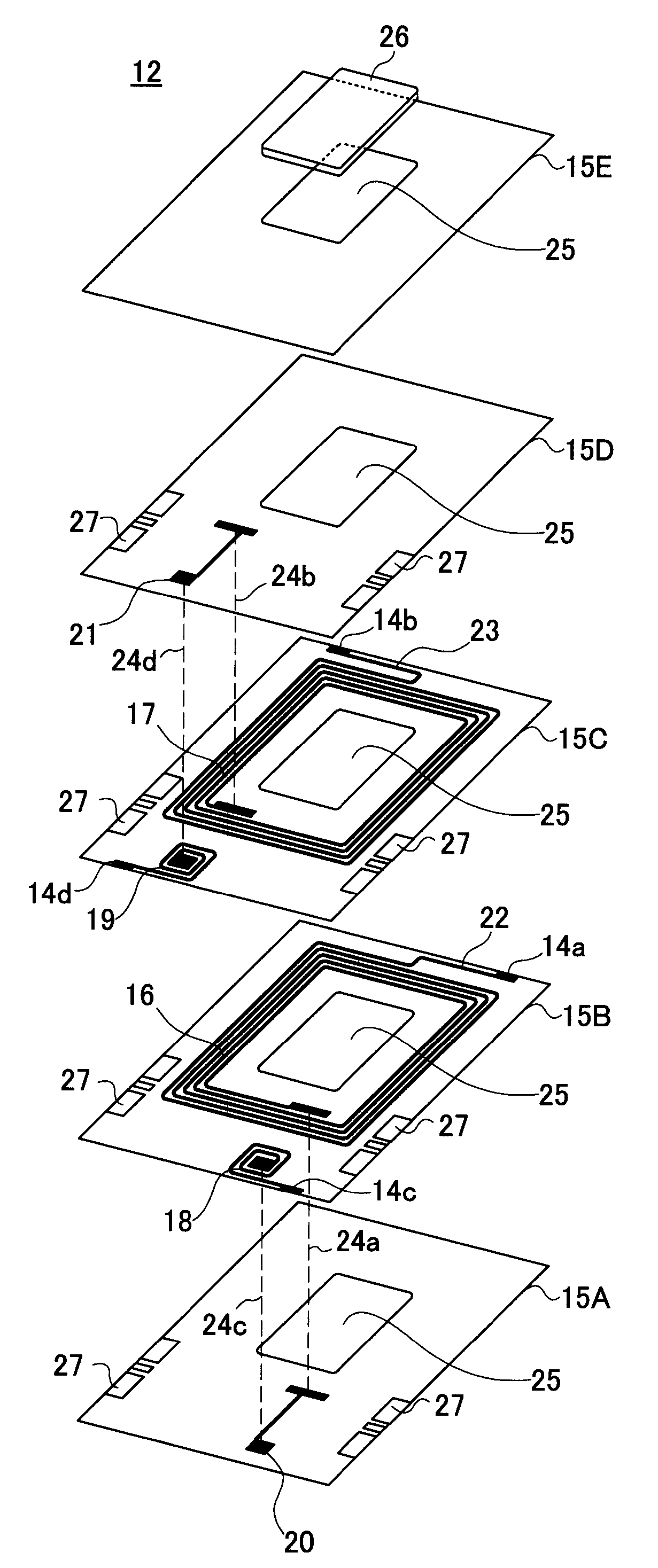
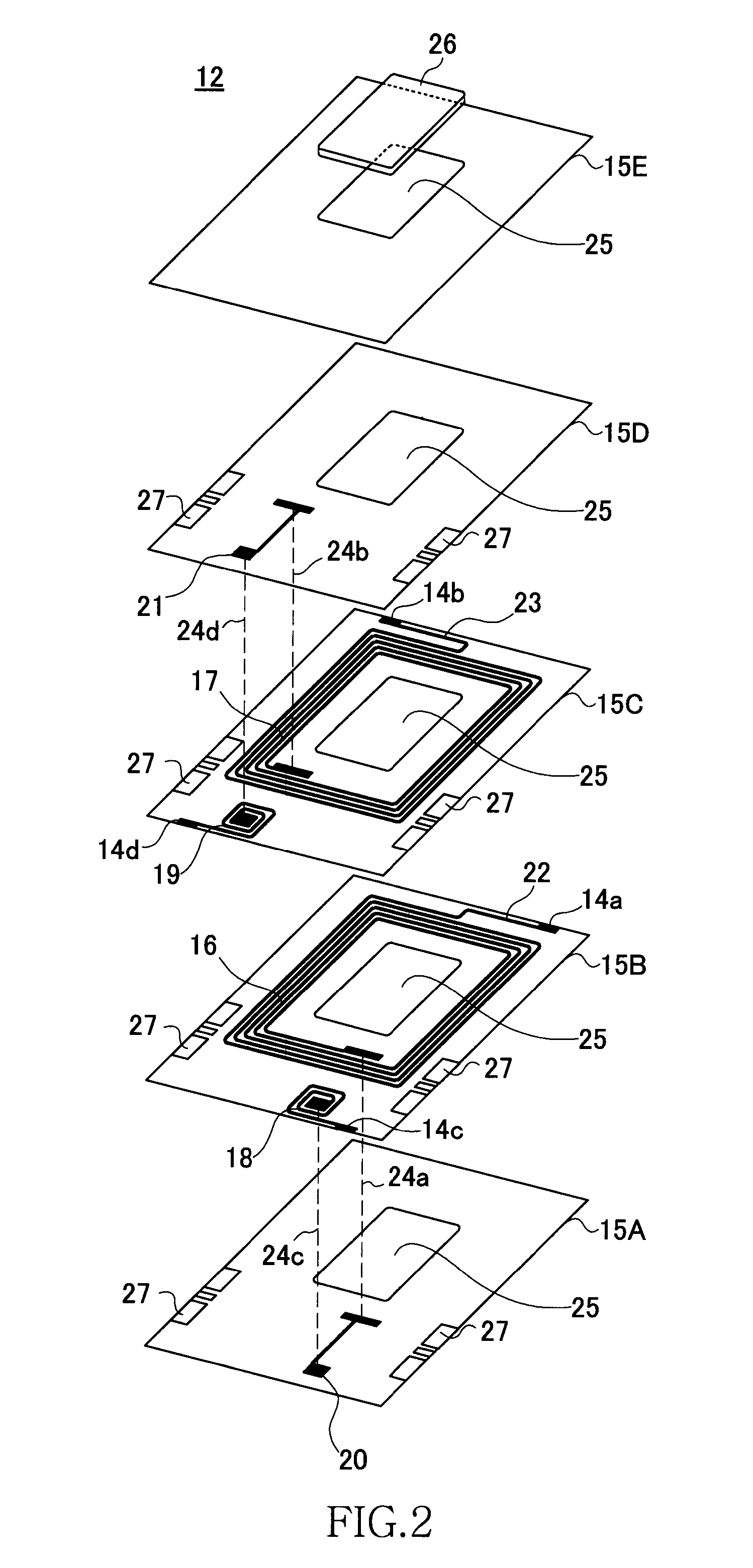
[0059]FIG. 4 is a schematic exploded perspective view showing the structure of the common mode choke coil 200 of the present invention, and shows the detailed structure of the layer assembly 12. Therefore, the magnetic substrates 11A, 11B and the magnetic body 26 in FIG. 4 are omitted.

[0060]As shown in FIG. 4, the characteristic features of the common mode choke coil 200 are that the common mode choke coil 200 has a three-layer layer assembly 12, and that the first contact conductor 20 and the second contact conductor 21 are both formed on the third insulation layer 150. The first coil conductor 16 and the third coil conductor 18 are formed on the first insulation layer 15A, and the second coil conductor 17 and the fourth coil conductor 19 are formed on the second insulation layer 15B. Since the other structural aspects are the same as in first embodiment, the same symbols are used to refer to the constituent elements that are the same in both embodiments, and no detailed descripti...

third embodiment

[0061]FIG. 5 is a schematic exploded perspective view showing the structure of the common mode choke coil 300 of the present invention, and shows the detailed structure of the layer assembly 12. Therefore, the magnetic substrates 11A, 11B and the magnetic body 26 in FIG. 5 are omitted.

[0062]As shown in FIG. 5, the characteristic features of the common mode choke coil 300 are that the common mode choke coil 300 has a three-layer layer assembly 12, and that the first contact conductor 20 and the second contact conductor 21 are both formed on the second insulation layer 15B. In other words, the first and second contact conductors 20, 21 are formed between the coil layers. Since the other structural aspects are the same as in first embodiment, the same symbols are used to refer to the constituent elements that are the same in both embodiments, and no detailed description thereof will be given. According to the present embodiment, one of the insulation layers can be omitted, and a commo...


PUM

PropertyMeasurementUnit
frequencyaaaaaaaaaa
impedanceaaaaaaaaaa
thicknessaaaaaaaaaa

Abstract

A common mode choke coil is provided with first and second coil conductors that are magnetically coupled to each other, a third coil conductor that is electrically connected in series to the first coil conductor and substantially not magnetically coupled to the first coil conductor, a fourth coil conductor that is electrically connected in series to the second coil conductor and substantially not magnetically coupled to the second coil conductor, a first contact conductor for connecting the third coil conductor with the inner end of the first coil conductor, and a second contact conductor for connecting the fourth coil conductor with the inner end of the second coil conductor. The third coil conductor and the fourth coil conductor are substantially not magnetically coupled, and are in a linear symmetrical relationship based on a prescribed center line.

Description

CROSS-REFERENCE TO RELATED APPLICATIONS[0001]This application claims foreign priority under 35 U.S.C. §119(a)-(d) of Japanese Patent Application No. 2007-134-159, filed May 21, 2007, which application is hereby incorporated herein by reference in its entirety.TECHNICAL FIELD[0002]The present invention relates to a common mode choke coil, and particularly relates to a common mode choke coil provided with characteristic impedance adjustment coils.BACKGROUND OF THE INVENTION[0003]A differential transmission system is known as one of the transmission systems for transmitting a digital signal between electronic devices. The differential transmission system is a system in which digital signals each having opposite phases are inputted in a single pair of signal lines, and external noise generated from the signal lines or radiation noise is cancelled out through differential transmission. Since noise is reduced by the cancellation of external noise, a signal can be transmitted at a low ampl...

Claims


Application Information

Patent Timeline
Patent Type & Authority Patents(United States)
IPC IPC(8): H01F5/00H01F27/28
CPCH01F17/0013H03H2001/0092H01F2017/0093H01F27/027
Inventor ITO, TOMOKAZUOKUMURA, TAKESHITOMONARI, TOSHIO
Owner TDK CORPARATION
Why Eureka
Try Eureka