
Integrated proximity-to-optical transceiver chip

a technology of optical transceivers and integrated circuit chips, which is applied in the direction of optical elements, instruments, semiconductor/solid-state device details, etc., can solve the problems of limiting the number of rows of wire bonds, the bottleneck is expected to worsen, and the advances in inter-chip communication technology cannot match the advances of semiconductor technology, so as to facilitate data transfer and high aggregate bandwidth

Active Publication Date: 2010-04-06
ORACLE INT CORP
View PDF22 Cites 13 Cited by
  • Summary
  • Abstract
  • Description
  • Claims
  • Application Information

AI Technical Summary

Benefits of technology

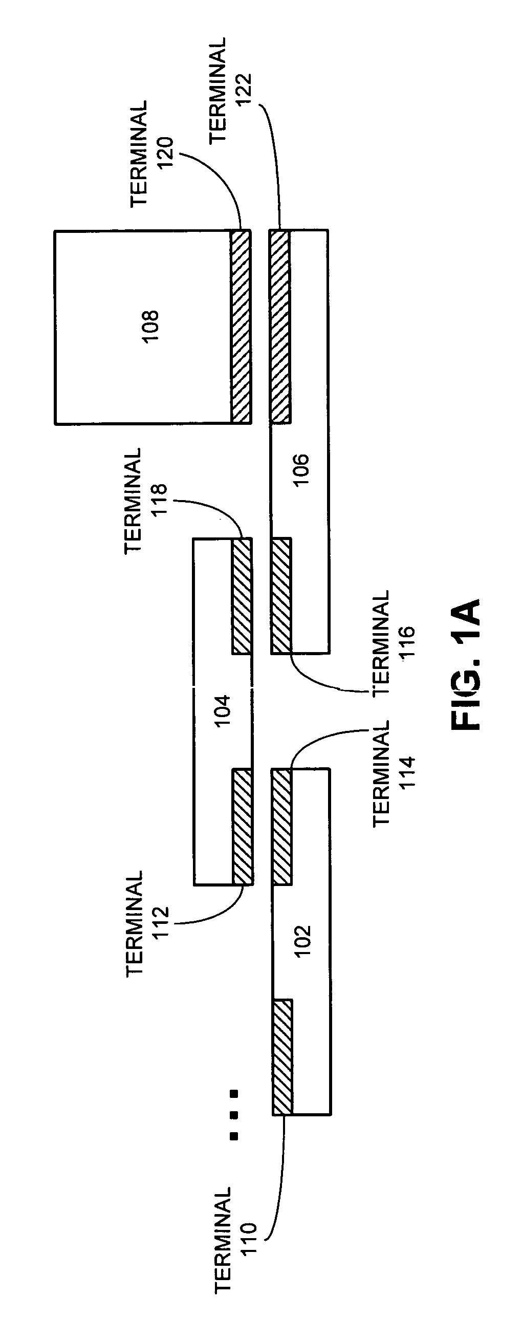
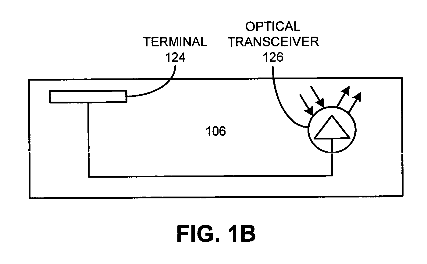
[0018]One embodiment of the present invention provides a system that facilitates high-speed data transfer between integrated circuit chips. The system contains a first integrated circuit chip, which includes a capacitive receiver and an electrical-to-optical transceiver. The capacitive receiver receives a capacitively coupled voltage signal transmitted from a corresponding capacitive transmitter located on a second integrated circuit chip and converts the capacitively coupled voltage signal into an electrical signal. The electrical-to-optical transceiver converts the electrical signal to an optical signal and transmits the optical signal to an optical device through optical coupling.
[0021]In a variation on this embodiment, the first integrated circuit chip is not permanently attached to the optical receiver in the optical connector, whereby the first integrated circuit chip can be easily remated to other optical connectors and to other integrated circuit chips.
[0027]In a variation on this embodiment, the first integrated circuit chip includes a multiplexing mechanism, which facilitates transferring data at high aggregate bandwidths.

Problems solved by technology

However, these semiconductor chips still need to communicate with other chips, and unfortunately, these advances in semiconductor technology have not been matched by corresponding advances in inter-chip communication technology.
This problem is creating a bottleneck that is expected to worsen as semiconductor integration densities continue to increase.
Furthermore, wire bonds are typically limited to a few rows.
Hence, wire bonds generally cannot be used to provide a large fully populated two-dimensional array of terminals.
Also, wire bonds are permanent, and do not permit rematabilty of connectors.
A significant limitation for conventional electrical interconnects is that they are designed either for moderate density (e.g. wire-bonds, or BGA) or for remateability (i.e. connectors), but not simultaneously for both.
However, these connections have low-density and support only moderate bandwidth per connection.
These conversion operations presently cause a number of electrical bottlenecks.
This bottleneck is more difficult to solve, due to a lack of very high-speed bus standards among processor vendors, and because there is no credible thermal or packaging solution that allows high-density optical technology to be combined with silicon processors.
Furthermore, there are currently no accepted electrical interconnect solutions for aggregate off-chip bandwidth beyond 1-2 Tbps.
Note that conventional technologies, such as wire-bonding, cannot scale to this bandwidth capacity.

Method used


Image

  • Integrated proximity-to-optical transceiver chip
  • Integrated proximity-to-optical transceiver chip
  • Integrated proximity-to-optical transceiver chip

Examples


Embodiment Construction

[0031]The following description is presented to enable any person skilled in the art to make and use the invention, and is provided in the context of a particular application and its requirements. Various modifications to the disclosed embodiments will be readily apparent to those skilled in the art, and the general principles defined herein may be applied to other embodiments and applications without departing from the spirit and scope of the present invention. Thus, the present invention is not limited to the embodiments shown, but is to be accorded the widest scope consistent with the principles and features disclosed herein.

Integrated Proximity-to-Optical Transceiver (IPOT) Chip

[0032]The present invention uses Proximity Communication techniques to provide a high-density, remateable connector that connects directly to and disconnects directly from high-speed electrical connections on the surface of an integrated optical transceiver chip. In one embodiment of the present invention...


PUM


Abstract

A system that facilitates high-speed data transfer between integrated circuit chips. The system contains a first integrated circuit chip, which includes a capacitive receiver and an electrical-to-optical transceiver. The capacitive receiver receives a capacitively coupled voltage signal transmitted from a corresponding capacitive transmitter located on a second integrated circuit chip and converts the capacitively coupled voltage signal into an electrical signal. The electrical-to-optical transceiver converts the electrical signal to an optical signal and transmits the optical signal to an optical device through optical coupling.

Description

RELATED APPLICATION[0001]This application is a continuation-in-part of a U.S. patent application, entitled “Optical Communication Between Face-to-Face Semiconductor Chips,” by inventor Robert J. Drost and William S. Coates, having Ser. No. 10 / 816,762 and a filing date of 2 Apr. 2004 now U.S. Pat. No. 7,369,726. This application hereby claims priority under 35 U.S.C. §120 to the above-listed patent application. Moreover, the above-listed application is hereby incorporated by reference. This application also hereby claims priority under 35 U.S.C. §119 to U.S. Provisional Patent Application No. 60 / 583,941 filed 28 Jun. 2004, entitled “Integrated Proximity-to-Optical Transceiver Chip,” by inventors Ashok V. Krishnamoorthy, Danny Cohen, and Robert J. Drost.GOVERNMENT LICENSE RIGHTS[0002]This invention was made with United States Government support under Contract No. NBCH020055 awarded by the Defense Advanced Research Projects Administration. The United States Government has certain right...

Claims


Application Information

Patent Timeline
IPC IPC(8): H04B10/00
CPCG02B6/43H01L25/0652H01L25/0657G02B6/4204H01L2924/0002H01L2225/06527H01L2924/00
Inventor KRISHNAMOORTHY, ASHOK V.COHEN, DANNYDROST, ROBERT J.
Owner ORACLE INT CORP
Learn More