Magnetic resonance imaging with adjustable fixture apparatus

Inactive Publication Date: 2010-04-06
FONAR
View PDF34 Cites 47 Cited by
  • Summary
  • Abstract
  • Description
  • Claims
  • Application Information

AI Technical Summary

Benefits of technology

[0009]One aspect of the present invention provides a magnetic resonance imaging system which includes a magnetic resonance apparatus having a structure including elements defining a patient-receiving gap and also including a patient support moveable relative to the structure through a range of support positions. The imaging system according to this aspect of the invention desirably includes a fixture positioning apparatus and a fixture. The fixture positioning apparatus is operative to secure the fixture to the patient support and to permit adjustment of the fixture relative to the patient support over a range of fixture positions. Most preferably, the range of fixture positions allowed by the fixture positioning apparatus is limited so that for any position of the fixture within the range of fixture positions, the fixture will remain clear of the elements of the structure defining the gap during movement of the patient support. A system according to this aspect of the invention provides adjustability of the fixture as required to meet patient needs, but also provides significant safety benefits. The fixture positioning apparatus prevents the technician from accidentally setting the position of the fixture relative to the support in such a manner that movement of the support will cause the fixture to crash into the gap-defining structure of the magnet.
[0014]The preferred positioning apparatus and magnetic resonance systems in accordance with these aspects of the present invention provide secure attachment of fixtures to the patient support and are operable with the support in a vertical orientation, as well as other orientations such as a horizontal orientation, a Trendelenburg orientation in which the head end of the fixture, with the patient's head is lower than the foot end, and intermediate orientations. The most preferred structures in accordance with these aspects of the invention provide the versatility needed to accommodate a wide range of procedures using various fixtures disposed in various locations, and also provide for quick changes of fixtures and positions. Moreover, the preferred apparatus and systems according to these aspects of the invention provide significant safety benefits.
[0016]Another aspect of the present invention is a device for use in magnetic resonance imaging. The device comprises a base member and first and second antenna loop portions, which are threaded through the base member. The base member is orientable relative to a patient's anatomy such that the first antenna loop portion is adjacent to an anterior surface of the patient and said second loop portion is adjacent to a posterior surface of the patent. Devices implemented in accordance with this aspect of the invention advantageously improve the capability of magnetic resonance imaging by making it possible to capture magnetic resonance signals emanating from either or both the anterior and posterior surfaces of a patient's anatomy.
[0024]An additional aspect of the present invention is a system comprising a magnetic resonance imaging apparatus having a structure including opposed elements defining a patient receiving space therebetween, a magnet axis extending substantially horizontally and a patient support. The patient support is capable of supporting a patient in a substantially upright position and is located within the structure. The system further includes a support arm mounted to the patient support such that the support arm projects from the patient support. The system advantageously allows a patient to be imaged in a variety of positions, including the standing or sitting position while the support arm holds a device used as part of the imaging process.

Problems solved by technology

Desirably, the range of positions in the lateral direction is limited so that, for any position of the fixture within this range of positions in the lateral direction, the fixture is disposed entirely between the longitudinal edges of the patient support.

Method used


Image

  • Magnetic resonance imaging with adjustable fixture apparatus
  • Magnetic resonance imaging with adjustable fixture apparatus
  • Magnetic resonance imaging with adjustable fixture apparatus

Examples


Embodiment Construction

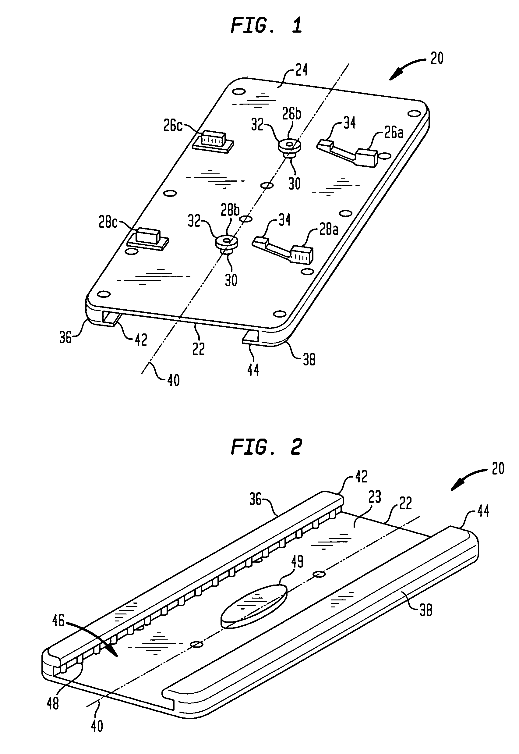
[0048]A positioning apparatus in accordance with one embodiment of the invention includes a mounting unit 20 (FIGS. 1 and 2). The mounting unit includes a lower plate 22 having a bottom surface 24. A first set of guide elements 26a-26c projects from the bottom surface in a row extending across the bottom plate. A second set of guide elements 28a-28c also projects from the bottom surface. The guide elements of the second set are arranged in a row parallel to the row formed by the first set of guide elements 26. The first set of guide elements includes a center guide element 26b in the form of a shoulder bolt having a relatively small diameter neck portion 30 adjacent the bottom face 24 of the bottom plate and having a relatively large diameter head 32 spaced away from the bottom face 24. The remaining guide units 26a and 26c of the first set are generally rectangular, solid elements. The guide elements 28 of the second set include end elements 28a and 28c, similar to the end elements...


PUM


Abstract

A fixture such as a local receiver coil is secured to the patient support of a magnetic resonance imaging system so that the fixture remains in position relative to the support even when the support is in a vertical orientation. The positioning apparatus is arranged to allow adjustment of the fixture position, but to limit such adjustment so that the fixture cannot interfere with the poles or other elements defining the patient-receiving gap of the magnet during movement of the patient support.

Description

CROSS-REFERENCE TO RELATED APPLICATIONS[0001]The present application is a continuation-in-part of U.S. patent application Ser. No. 10 / 131,843, filed on Apr. 25, 2002 now U.S. Pat. No. 7,551,954 and entitled “Magnetic Resonance Imaging Fixture Mounting,” the disclosure of which is incorporated by reference herein in its entirety.FIELD OF INVENTION[0002]The present invention relates to the art of magnetic resonance imaging.BACKGROUND OF THE INVENTION[0003]In magnetic resonance imaging (“MRI”), the body of a subject to be imaged as, for example, the body of a medical patient, is subjected to a strong static magnetic field. Radio frequency (“RF”) excitation signals are applied to the subject. This causes the tissues of the subject's body to emit minuscule radio frequency signals referred to herein as “magnetic resonance signals.” During the procedure, magnetic field gradients are applied so that, during different portions of the procedure, the strength of the static magnetic field varie...

Claims


Application Information

Patent Timeline
Patent Type & Authority Patents(United States)
IPC IPC(8): A61B5/055G01R33/28G01R33/341
CPCA61B5/0555G01R33/28G01R33/341A61B5/055
Inventor GREEN, CHARLES A.VOTRUBA, JAN
Owner FONAR
Why Eureka
Try Eureka