Automated warehousing and cargo loading system

a cargo loading and warehousing technology, applied in the field of material handling systems, can solve the problems of increasing the quantity and cost of labor required to perform the shipping and receiving functions, increasing the cost of warehouse operations, and increasing the cost of direct labor costs, so as to reduce the cost of personnel and associated labor, the effect of reducing the operational cost of the warehouse and reducing the cost of the operation

Inactive Publication Date: 2010-04-13
RALLIS JOHN H
View PDF44 Cites 158 Cited by
  • Summary
  • Abstract
  • Description
  • Claims
  • Application Information

AI Technical Summary

Benefits of technology

[0009]The present invention has solved the problems cited above, and is a warehousing system having automated cargo storage and loading/unloading systems. The invention is designed to operate in conjunction with, or as a replacement for, the conventional forklift loading opera

Problems solved by technology

The cost of purchasing, constructing and maintaining the dedicated portions of the facility contributes significantly to the cost of the warehouse operation, and, during down-time, occupies valuable space that could be used in a more productive manner.
Another disadvantage of conventional warehouse shipping facilities is the quantity and cost of labor required to perform the shipping and receiving functions.
Considering the number of docking bays and transport vehicles which may be operating simultaneously, the direct labor costs quickly accumulate.
Because many of these opera

Method used


Image

  • Automated warehousing and cargo loading system
  • Automated warehousing and cargo loading system
  • Automated warehousing and cargo loading system

Examples


Embodiment Construction

a. Overview

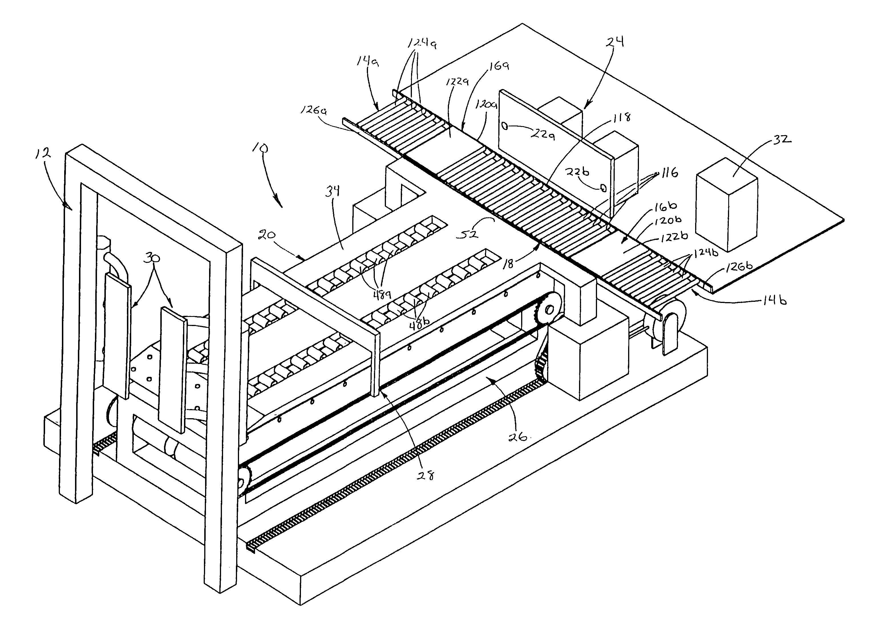
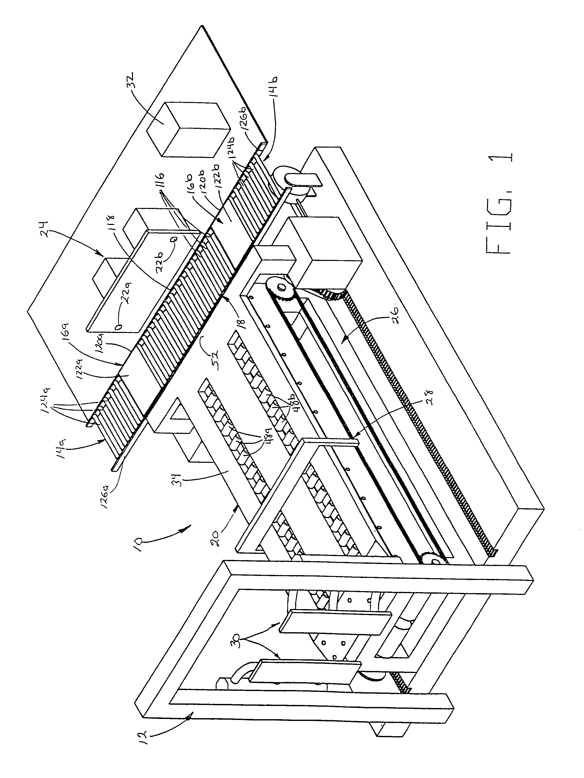
[0051]FIG. 1 shows an automated cargo loading system 10 in accordance with the present invention, installed adjoining a truck docking bay door frame 12 in a typical warehouse facility. In the preferred embodiment, the invention comprises the following major elements which perform the following functions: The point of inventory (POI) conveyors 14a,b transport palletized goods between a source location, such as a storage unit or production line, and the feed control (FC) conveyors 16a,b. The feed control (FC) conveyors 16a,b provide controlled, sequential transfer of the palletized cargo between the POI conveyors 14a,b and the dock transfer (DT) conveyor 18. The dock transfer (DT) conveyor 18 moves palletized cargo from the FC conveyors 16a,b into alignment with the extensible dock 20 and serves as a staging platform for palletized loads being transferred to or from the extensible dock 20. The feed control sensors 22a,b, which operate in conjunction with the FC conveyors 16...


PUM


Abstract

A warehousing system for palletized cargo, and an automated loading/unloading system for use with the same. The warehousing system includes a feed conveyer and a plurality of storage racks. A traveling conveyor carries the cargo from the feed conveyor to the individual racks, and from the racks to a loading/unloading conveyor which carries the cargo to the loading/unloading docks. The traveling conveyor rides on a wheeled chassis that is guided between the receiving and discharge locations on tracks. The storage racks are stackable in tiers, and the traveling conveyor has a deck that raises and lowers to be level therewith. The automated loading/unloading dock includes a rigid, extensible plate having an upper surface for supporting a load of palletized cargo, with a drive mechanism being mounted to the inner end of the plate to translate it in and out of the transport vehicle. The plate carries a load of palletized cargo into or out of the transport vehicle en masse. For loading, restraining doors hold the loaded cargo within the interior of the vehicle as the extensible dock is withdrawn. When unloading, a paddle is deployed above the upper surface of the lock member and is translated towards its inner end so as to push the cargo onto the loading/unloading conveyor.

Description

[0001]This application claims the benefit of U.S. Provisional Application(s) No. 60 / 397,471 filing date Jul. 19, 2002.BACKGROUND OF THE INVENTION[0002]a. Field of the Invention[0003]The present invention relates generally to material handling systems and, more particularly, to an automated warehousing system and an automated cargo loading system for the loading / unloading of palletized freight, bales and the like onto / from truck trailers or similar transport vehicles.[0004]b. Background Art[0005]It is common practice among major shipping companies, as well as large retail chains, manufacturers, and food processors, to maintain warehouse facilities that serve as national or regional distribution centers for the interim storage and distribution of goods. In general, the large quantities of goods being shipped and received at these warehouses demands that a significant portion of the facility be dedicated not only to storage but also to the transport operation which requires numerous tr...

Claims


Application Information

Patent Timeline
IPC IPC(8): B65F9/00B65G67/00
CPCB65G1/02B65G67/20B65G47/54B65G1/0407
Inventor RALLIS, JOHN H.
Owner RALLIS JOHN H
Why Eureka
Try Eureka