Method and system for transmitting and receiving data streams

a data stream and transmission method technology, applied in the field of transmission systems, can solve the problems of inefficiency and delay of transmission, loss of data transmission capacity,

Active Publication Date: 2010-04-13
LG ELECTRONICS INC
View PDF12 Cites 12 Cited by
  • Summary
  • Abstract
  • Description
  • Claims
  • Application Information

AI Technical Summary

Benefits of technology

[0012]Accordingly, the present invention is directed to a [title] that substantially obviates one or more problems due to limitations and disadvantages of the related art.
[0013]An object of the present invention is to provide a method of transmitting and receiving data streams having weight values applied to the data streams and selecting a group of antennas providing a maximum data throughput.
[0014]Another object of the present invention is to provide a method of transmitting and receiving data streams by having weight values applied thereto.
[0015]Another object of the present invention is to provide a method of transmitting and receiving data streams by selecting a group of antennas providing a maximum data throughput.

Problems solved by technology

As a result, transmission may suffer inefficiency and delays due to underutilization of antennas and overuse of other antennas.
Moreover, time and resources could be wasted.
Therefore, the amount of data transmitted suffers.
If antennas 1 and 2 have strong signal strength compared to antennas 3 and 4, yet data stream 1 does not have much data to transmit whereas data stream 2 does, the fixed configuration would cause delays in transmitting data stream 2 due to weak signals and data overload.
On the contrary, antennas 1 and 2 do not have much data to transmit, resulting in underutilization of resources.
Another disadvantage of the existing diversity scheme is that antenna signal strengths are not considered prior to transmitting data through them.
As a result, inefficient as well as ineffective data transmission could occur.
In addition, the amount of data transmitted suffers.
By transmitting a data stream through both antennas, the transmission in antenna 2 would suffer and considered inefficient.

Method used


Image

  • Method and system for transmitting and receiving data streams
  • Method and system for transmitting and receiving data streams
  • Method and system for transmitting and receiving data streams

Examples


Embodiment Construction

[0027]Reference will now be made in detail to the preferred embodiments of the present invention, examples of which are illustrated in the accompanying drawings. Wherever possible, the same reference numbers will be used throughout the drawings to refer to the same or like parts.

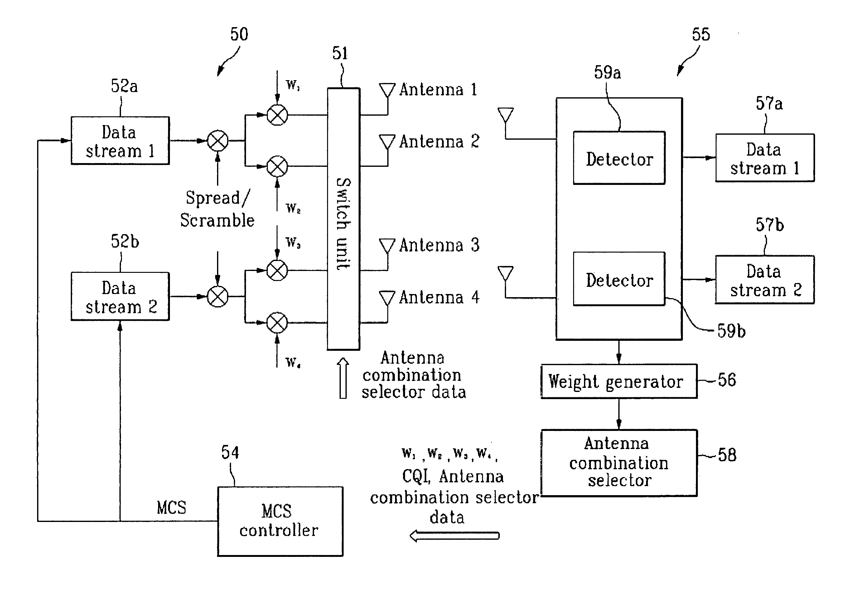
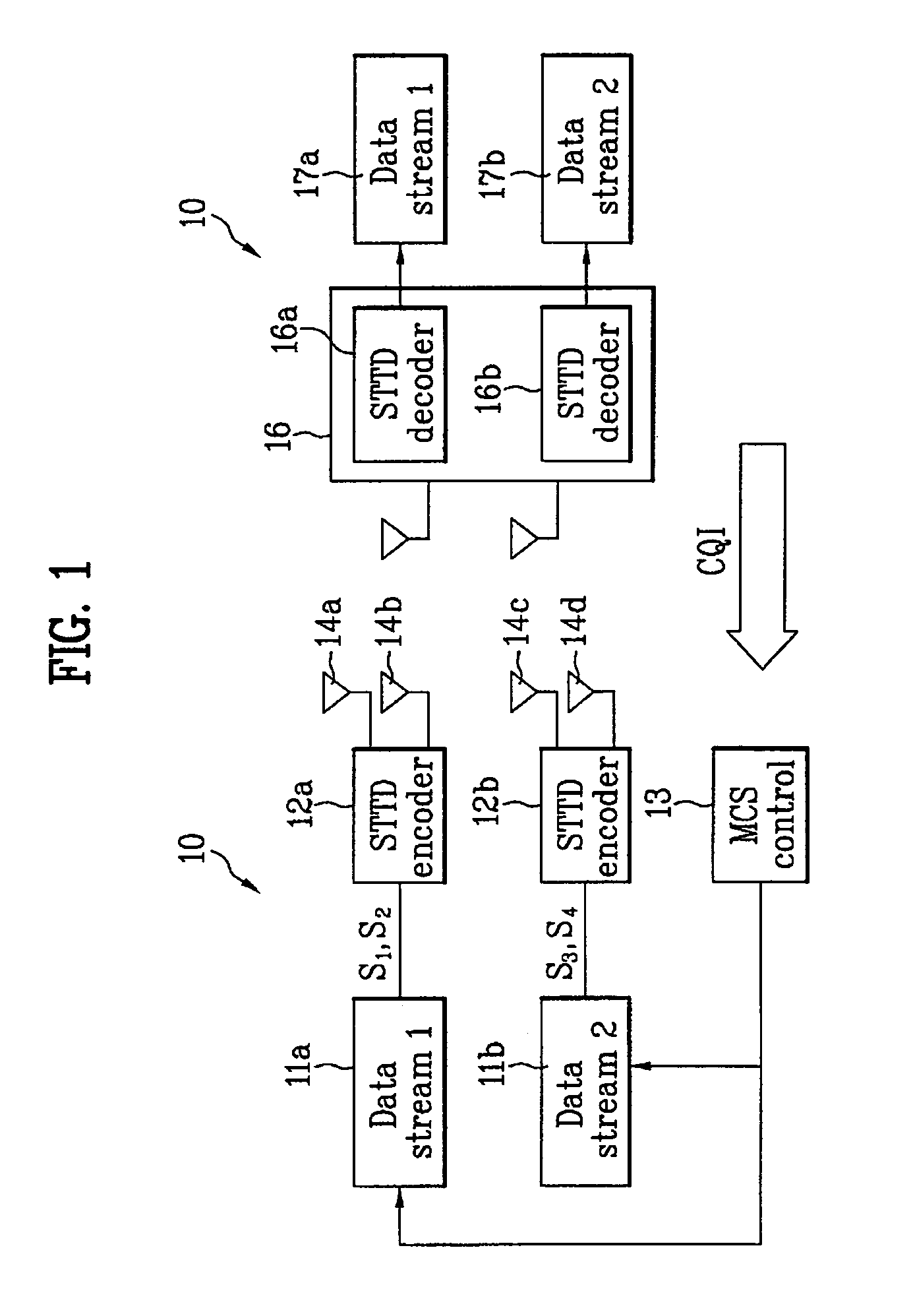
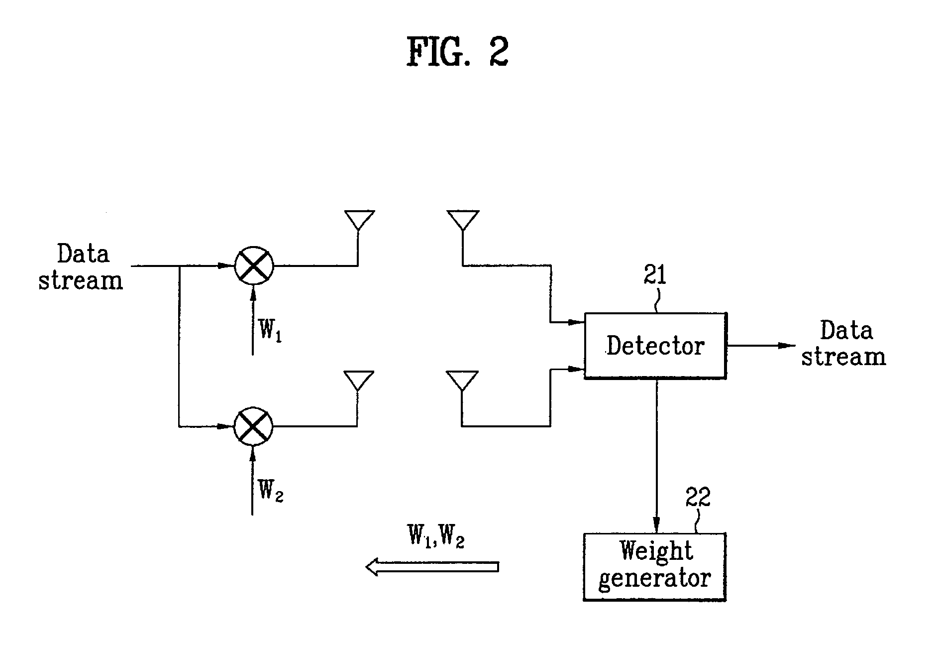
[0028]As a part of diversity transmission scheme, Space Time Transmit Diversity (STTD) and modes 1 and 2 of Transmit Antenna Array (TxAA) are widely used. The STTD scheme is an open loop technique using two antennas to exploit diversity. More specifically, the STTD employs space-time coding to achieve diversity. Furthermore, the STTD scheme is applicable to all of the downlink physical channel except Synchronization Channel (SCH) of Wideband Code Division Multiple Access (WCDMA). Because STTD scheme does not require feedback signal, delays caused by feedback transmission does not affect transmission in the STTD scheme. The operation of STTD is further explained using the following Table 1.

[0029]

TABLE 1tt + T...


PUM


Abstract

A method and system for transmitting and receiving data using a plurality of antennas are disclosed. The method of transmitting includes the steps of receiving feedback information from a receiving end, the feedback information including group selection information and weight values for the plurality of antennas, grouping the plurality of antennas into a plurality of antenna groups based on the group selection information included in the feedback information, and transmitting, to a receiving end, a plurality of data streams through the plurality of antenna groups, respectively, based on the weight values.

Description

CROSS REFERENCE TO RELATED APPLICATIONS[0001]This application claims the benefit of Korean Application No. 10-2004-0009397 and 10-2004-0054802 filed on Feb. 12, 2004 and Jul. 14, 2004, respectively, which are hereby incorporated by reference.[0002]This application claims the benefit of U.S. Provisional Application No. 60 / 543,404, filed on Feb. 11, 2004, in the name of inventors Bonghoe KIM, Dongyoun SEO, and Hyounghee KOO, titled “METHOD OF CLOSED LOOP STTD WITH SUBGROUP RATE CONTROL . . . TxAA WITH SUBGROUP RATE CONTROL WITH MULTIPLE TRANSMIT AND RECEIVE ANTENNAS,” which is hereby incorporated by reference.BACKGROUND OF THE INVENTION[0003]1. Field of the Invention[0004]The present invention relates to a transmission system and more particularly, to a method of transmitting and receiving data streams using a plurality of antennas. Although the present invention is suitable for a wide scope of applications, it is particularly suitable for grouping a plurality of antennas into sub-gro...

Claims


Application Information

Patent Timeline
Patent Type & Authority Patents(United States)
IPC IPC(8): H04B7/02H04L1/02
CPCH04B7/0417H04B7/0426H04B7/0632H04B7/0634H04B7/0671H04B7/0691H04B7/0669H04L1/0026H04L1/0003
Inventor KIM, BONG HOESEO, DONG YOUNAHN, JOON KUIKIM, HAK SEONGWON, SEUNG HWANROH, DONG WOOK
Owner LG ELECTRONICS INC
Why Eureka
Try Eureka