
Method and device for controlling a drive unit

a technology of drive unit and control device, which is applied in the direction of electric control, braking system, instruments, etc., can solve the problems of inability to reproduce the behavior of the vehicle during a load reversal, and inability to cut off the cylinder

Inactive Publication Date: 2010-04-13
ROBERT BOSCH GMBH
View PDF12 Cites 6 Cited by
  • Summary
  • Abstract
  • Description
  • Claims
  • Application Information

AI Technical Summary

Benefits of technology

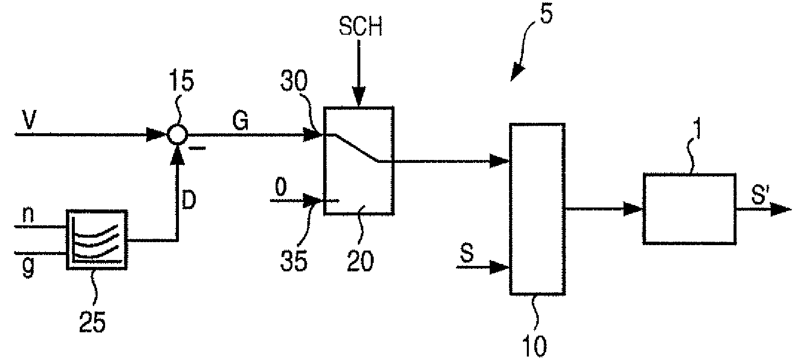
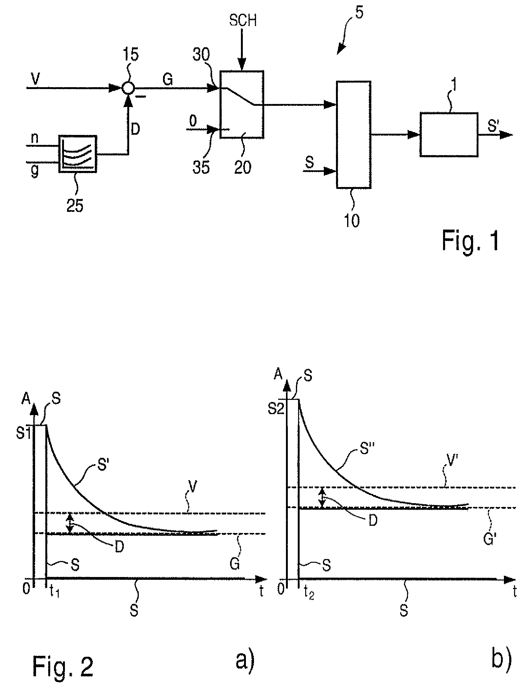
The present invention provides a method and device for controlling a drive unit that can prevent abrupt load reversals in a reproducible manner. This is achieved by forming a limiting value for the setpoint value of the output variable of the drive unit based on its loss value. This limiting value remains constant regardless of the magnitude of the loss value, so it can be easily implemented and adapted to the operating state of the drive unit. The setpoint value is filtered using a low pass filter to further optimize the load reversal damping. Overall, this invention provides a simple and reliable solution for preventing abrupt load reversals in a drive unit.

Problems solved by technology

Often a cutoff of the cylinders is not possible for reasons that do not depend on the formation of the threshold value for the engine torque, for example in order to ensure a tank ventilation or a sufficient catalytic converter temperature or if the engine speed is close to the idling setpoint speed.
This approach is problematic in that the behavior of the vehicle during a load reversal, i.e. during the transition from the acceleration condition into the overrun condition is not reproducible since the distance of the minimum torque from the clutch zero torque differs as a function of the clutch zero torque or of the torque loss.

Method used


Image

  • Method and device for controlling a drive unit
  • Method and device for controlling a drive unit

Examples


Embodiment Construction

[0016]In FIG. 1, 5 indicates a device according to the present invention in the form of a flow chart, which may be implemented, for example, by way of software and / or hardware in a control unit of a drive unit. In this instance, the drive unit may drive a motor vehicle, for example, and for this purpose may for example include a combustion engine. The combustion engine may be, for example, a spark-ignition engine or a diesel engine. In the case of the motor vehicle, the driver of the motor vehicle, for example, predefines a setpoint value for an output variable of the drive unit, for example, on an accelerator pedal by a suitable actuation. The output variable of the drive unit may be for example a torque or a power output or a variable derived from the torque and / or power output. In the following it is assumed by way of example that the output variable is a torque of the drive unit, for example, an engine torque. What is now considered is the transition from an acceleration conditi...


PUM


Abstract

A method and a device for controlling a drive unit are provided, which allow for a reproducible load reversal damping. For this purpose, a setpoint value for an output variable of the drive unit is limited so that an overrun fuel cutoff of the drive unit is prevented. A limiting value for the setpoint value for the output variable is formed as a function of a loss value of the drive unit.

Description

FIELD OF THE INVENTION[0001]The present invention is directed to a method and a device for controlling a drive unit.BACKGROUND INFORMATION[0002]Methods and devices for controlling a drive unit are already known, in which a setpoint value for an output variable of the drive unit is limited in such a way that an overrun fuel cutoff of the drive unit is prevented. If the driver of a vehicle releases the accelerator pedal at an engine speed that is greater than the idling speed, then he normally desires a deceleration of the vehicle by the drag torque of the engine including the operation of ancillary components of the vehicle. For the transition from an acceleration condition to an overrun condition of the vehicle, a setpoint value for the engine torque is filtered so that the vehicle is not decelerated too abruptly and no abrupt load reversal ensues. In this manner, a load reversal damping is implemented. Normally, what is to be achieved thereby is that following the filtering all cyl...

Claims


Application Information

Patent Timeline
Patent Type & Authority Patents(United States)
IPC IPC(8): B60T7/12F02D1/00
CPCF02D41/0005F02D41/123F02D41/1497Y02T10/42F02D2200/1006F02D2250/26F02D2041/1432Y02T10/40
Inventor LUDWIG, MARTINANZ, RUPRECHT
Owner ROBERT BOSCH GMBH
Learn More