Multiphase voltage sources driven AC—LED

a multi-phase voltage source and led technology, applied in the direction of process and machine control, pulse technique, instruments, etc., can solve the problems of lack of flexibility in light timing in prior art disclosing single-phase voltage source-based control, and failure to meet the need for a variety of ligh

Inactive Publication Date: 2010-04-20
EPISTAR CORP
View PDF17 Cites 8 Cited by
  • Summary
  • Abstract
  • Description
  • Claims
  • Application Information

AI Technical Summary

Benefits of technology

[0010]The prior art disclosing single-phase voltage source-based control lacks flexibility in light timing because of its fixed and unchangeable power cycle. The prior art fails to meet the need for a variety of light timing of the AC_LED.
[0011]In light of the aforesaid drawbacks of the prior art, it is a primary objective of the present invention to provide a method and system for an AC_LED to which the light timing is changeable through multiphase voltage sources control.
[0012]Another objective of the present invention is to provide a method and system for outputting different mixed light color in a wide range through a combination use of AC_LEDs with different color under multiphase voltage sources control.

Problems solved by technology

The prior art disclosing single-phase voltage source-based control lacks flexibility in light timing because of its fixed and unchangeable power cycle.
The prior art fails to meet the need for a variety of light timing of the AC_LED.

Method used


Image

  • Multiphase voltage sources driven AC—LED
  • Multiphase voltage sources driven AC—LED
  • Multiphase voltage sources driven AC—LED

Examples


first embodiment

[0071]FIGS. 2A to 2E show an AC_LED driven by two voltage sources with a phase difference of 40 degree of the present invention.

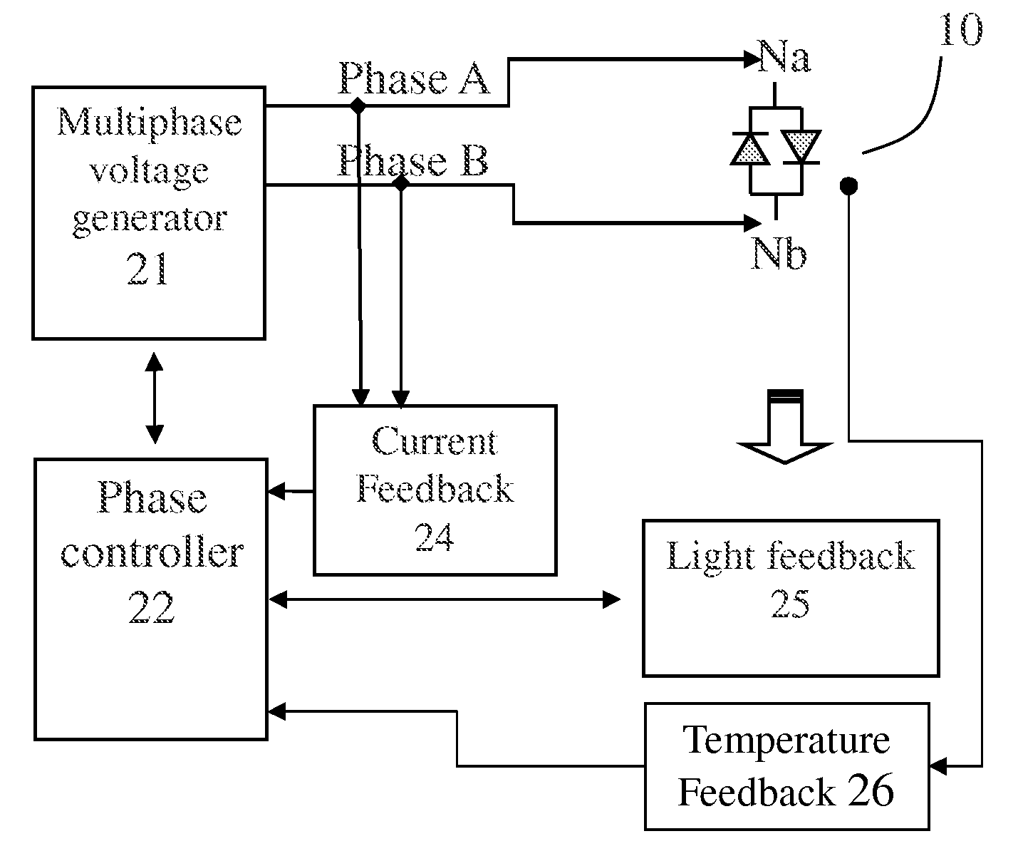
[0072]Referring to FIG. 2A, which shows an AC_LED driven by two voltage sources at different phases. An AC_LED 10 has a first terminal electrically coupling to node Na, and has a second terminal electrically coupling to node Nb. A multiphase voltage sources generator 21 modifies the input power from a power source 20 and outputs two voltage sources at phase A and phase B respectively. Phase A and phase B are then electrically coupled to node Na and node Nb respectively for driving the AC_LED 10.

[0073]Alternatively, a voltage phase controller 22 coupled to the multiphase voltage sources generator 21 is provided, so as to adjust the voltage phase of each voltage source output to control the light timing of the AC_LED 10. Furthermore, a control panel 23 can be alternatively included to couple to the phase controller 22 for the end user to set the voltage phase...

second embodiment

[0079]FIGS. 3A to 3D show an AC_LED driven by two voltage sources with a phase difference of 90 degree of the present invention.

[0080]Referring to FIG. 3A, which shows a voltage waveform with a phase lag of 90 degree. The abscissa shows a voltage phase with a scale of 0˜360 degree. The ordinate shows voltage with a scale of −200V˜+200V. Curve Va shows the voltage waveform at node Na. Curve Vb shows the voltage waveform at node Nb. Curve Vb lags curve Va in phase by 90 degree. Curve Va has a positive voltage peak of +156V at phase 90 degree and a negative voltage peak of −156V at phase 270 degree. Curve Vb has a positive voltage peak of +156V at phase 180 degree and a negative voltage peak of −156V at phase 360 degree.

[0081]Referring to FIG. 3B, which shows a voltage difference waveform between node Na and node Nb. The abscissa shows a voltage phase with a scale of 0˜360 degree. The ordinate shows a voltage difference with a scale of −300V˜+300V, indicating a positive voltage differe...

third embodiment

[0084]FIGS. 4A to 4D show an AC_LED driven by two voltage sources with a phase difference of 180 degree of the present invention.

[0085]Referring to FIG. 4A, which shows a voltage waveform with a phase lag of 180 degree. The abscissa shows a voltage phase with a scale of 0˜360 degree. The ordinate shows voltage with a scale of −200V˜+200V. Curve Va shows the voltage waveform at node Na. Curve Vb shows the voltage waveform at node Nb. Curve Vb has a 180 degree phase lag than curve Va. Curve Va has a positive voltage peak of +156V at phase 90 degree and a negative voltage peak of −156V at phase 270 degree. Curve Vb has a positive voltage peak of +156V at phase 270 degree and a negative voltage peak of −156V at phase 90 degree.

[0086]Referring to FIG. 4B, which shows a voltage difference waveform between node Na and node Nb. The abscissa shows voltage phase with a scale of 0˜360 degree. The ordinate shows a voltage difference with a scale of −400V˜+400V, indicating a positive voltage dif...


PUM


Abstract

Multiphase voltage sources are used in driving an AC_LED; different light timing is achieved by changing the relative phase or frequency of the voltage sources. Different light color mixing is also achieved when more than one AC_LED with different colors are combined to use.

Description

BACKGROUND OF THE INVENTION[0001]1. Field of the Invention[0002]The present invention relates to a light timing controlling method and device for an AC_LED, and more particularly, to a method and device for controlling light timing of an AC_LED by multiphase voltage sources.[0003]2. Description of the Prior Art[0004]FIGS. 1A to 1D show a traditional AC_LED driven by a single-phase voltage source.[0005]FIG. 1A shows a traditional controlling system for an AC_LED. A traditional AC_LED 10 is electrically coupling to a single-phase voltage source, for example, a nominal voltage of AC 110V. The AC_LED used in this invention is triggered by 90V as an example. An AC_LED 10 is composed of two DC_LEDs being electrically coupling with each other in electrically reverse direction. FIG. 1A shows that two DC_LEDs are arranged in a reversed direction, so that the two DC_LEDs are connected head to tail with shortest metal wires. The positive terminal of the first DC_LED (positive DC_LED) is connec...

Claims


Application Information

Patent Timeline
Patent Type & Authority Patents(United States)
IPC IPC(8): H05B37/02H01L33/00H02M5/04H03K17/78
CPCH05B33/0803H05B33/0815H05B33/0821H05B33/0872H05B33/0869H05B45/20H05B45/22H05B45/31H05B45/42H05B45/37H05B45/00
Inventor LIN, MING-TE
Owner EPISTAR CORP
Why Eureka
Try Eureka