Method and device for tracking eye movements

a technology of eye movements and tracking devices, applied in the field of eye movements tracking devices, can solve the problems of limitation of working freedom in the op field, unwelcome additional treatment costs, etc., and achieve the effect of simple determination of this compensation factor, rapid implementation of the method, and easy and fast measuremen

Inactive Publication Date: 2010-04-27
CARL ZEISS MEDITEC AG
View PDF12 Cites 23 Cited by
  • Summary
  • Abstract
  • Description
  • Claims
  • Application Information

AI Technical Summary

Benefits of technology

[0028]The compensation factor may be linear. For small angles in this geometrically measured parallax for example the approximation is true that the sine can be replaced by the argument. In addition, further approximation possibilities exist which allow a simple determination of this compensation factor. This linear (approximated) compensation factor can be easily and quickly measured and thus allows a swift implementation of the method according to the invention.

Problems solved by technology

However, this entails unwelcome additional treatment costs.
However, the illumination necessitates additional work for the doctor and a limitation of working freedom in the OP field.

Method used


Image

  • Method and device for tracking eye movements
  • Method and device for tracking eye movements
  • Method and device for tracking eye movements

Examples


Embodiment Construction

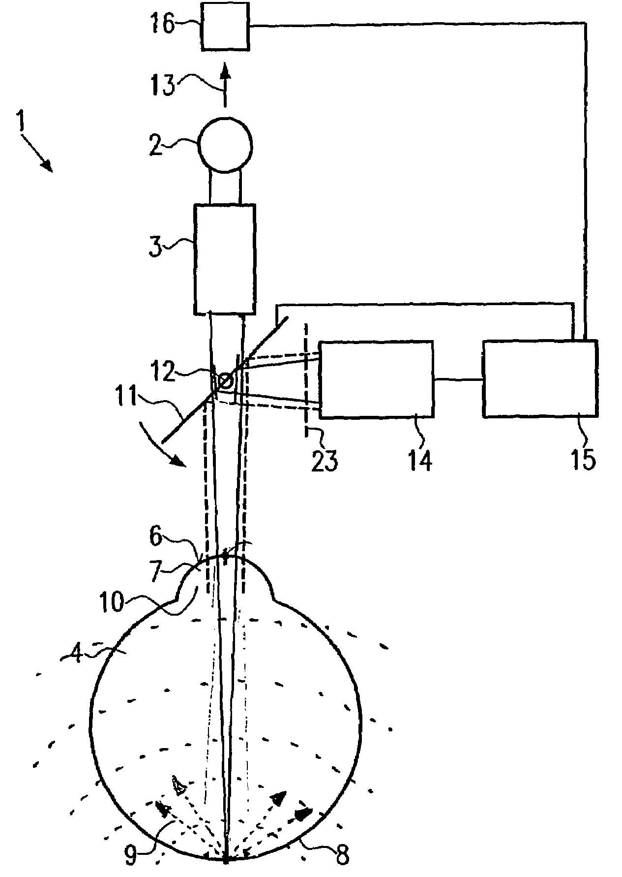
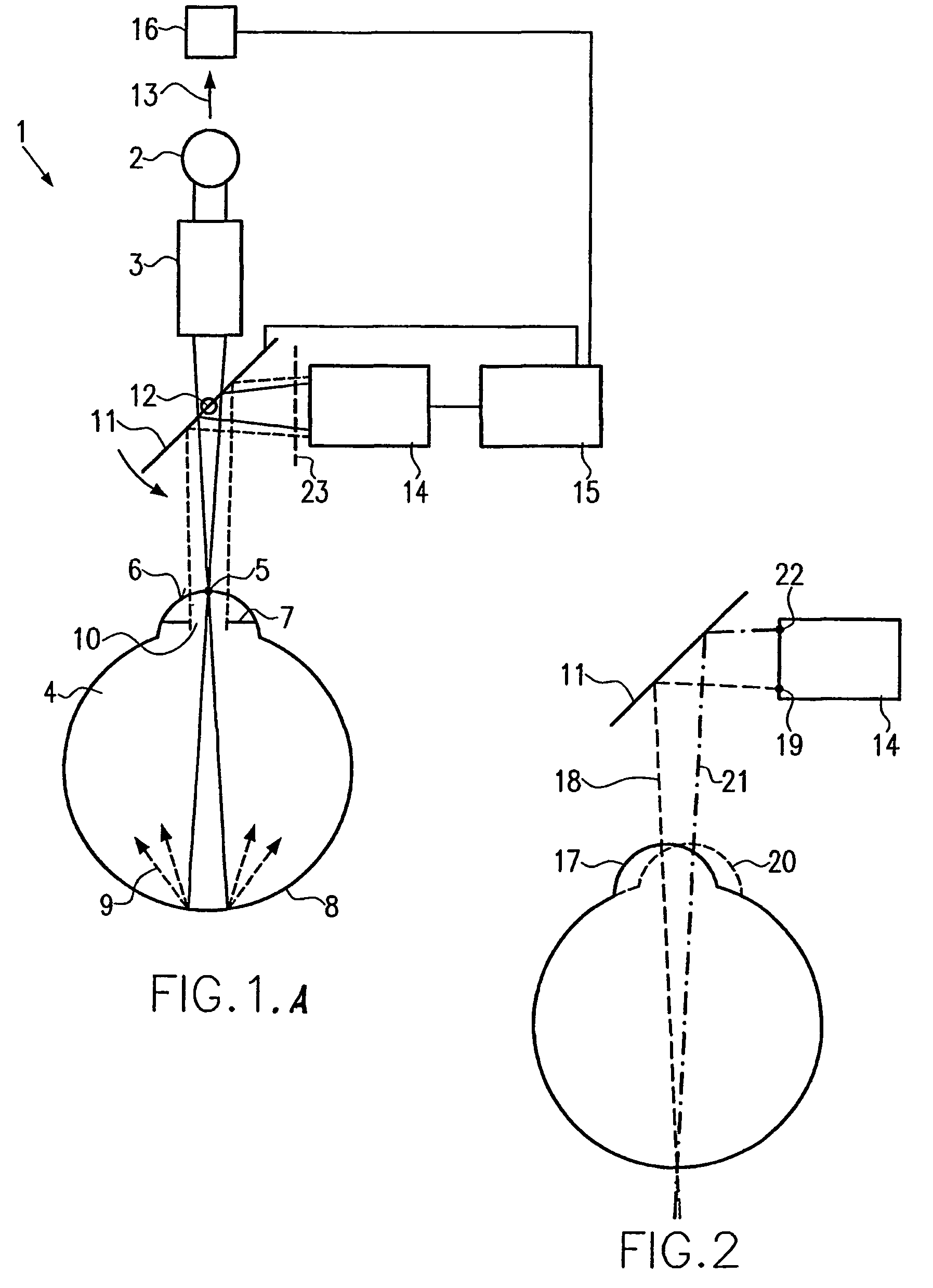
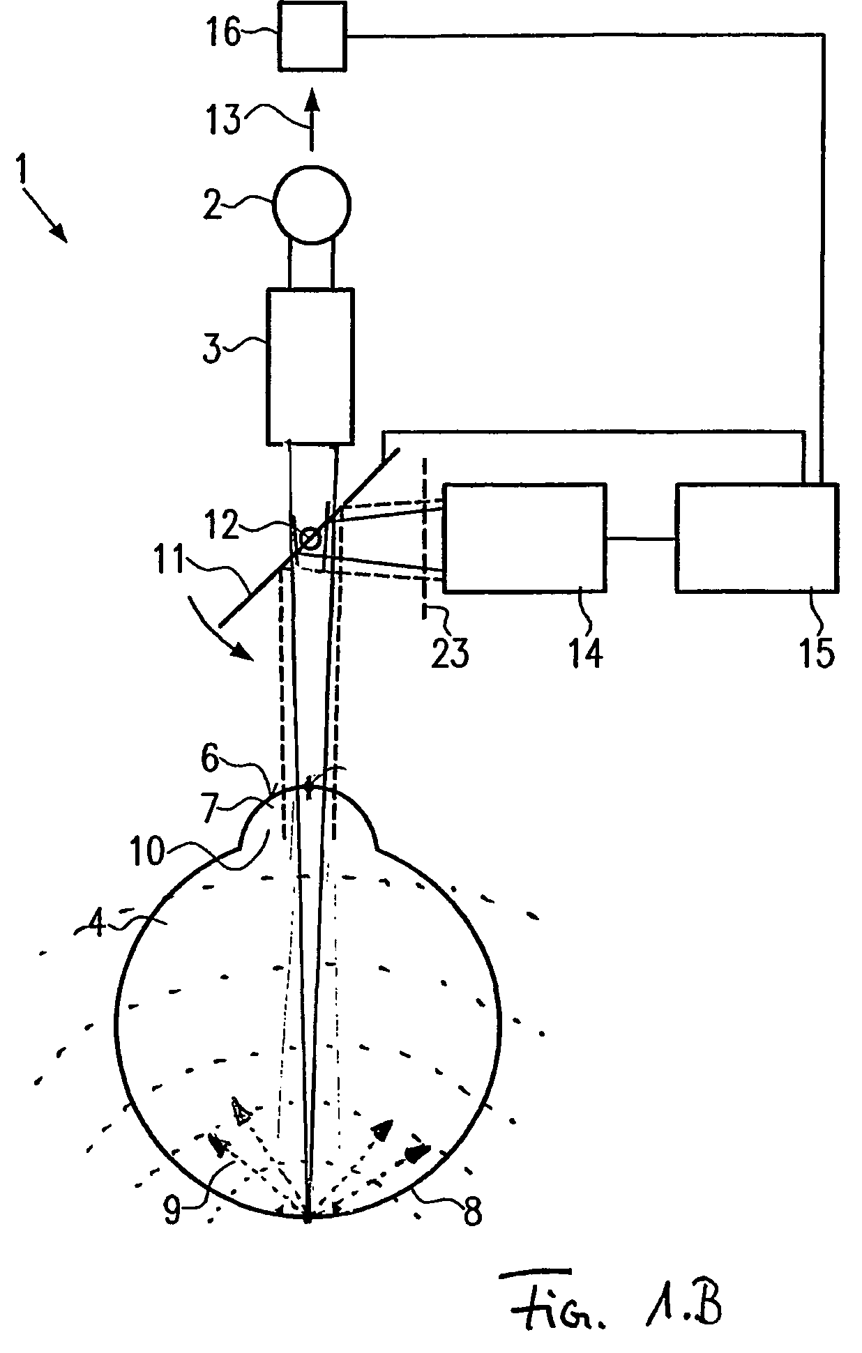
[0035]A device for tracking the eye movement 1 includes a light source 2, and a telescope 3. The light emitted from the light source 2 is guided via the telescope 3, which can be equipped with further optical apparatuses, for example such as lenses or similar, to an eye 4 of a person to be treated, not shown. The light is concentrated in a focal point 5. The focal point 5 lies on the cornea surface 6 of the iris 7 of the eye 4. After passing through the cornea surface 6 the light beam of the light source 2 broadens and strikes the retina 8 of the eye 4 as a broadened spot. The light source 2 is an infrared laser diode in the present embodiment. Its output is chosen such that the permissible irradiation intensity for the retina 8 is observed.

[0036]The light striking the retina 8 is diffusely reflected by same, as indicated by the arrow 9 in FIG. 1. The light 9 reflected from the retina 8 leads to a homogenous illumination of the pupil 10.

[0037]After the reflected light 9 has passed t...


PUM


Abstract

A method and a device for tracking eye movements that ensure a reliable tracking of eye movements with simple operation. To this end, irradiation ensues through the pupil from outside the eye. Light emitted from the pupil is used to determine the position of the eye.

Description

BACKGROUND[0001]The present invention relates to a method and a device for tracking eye movements.[0002]Refractive laser surgery of the cornea, in particular with ablative excimer lasers (ArF—wavelength 193 nm) as OP laser, has become an established method of treating refractive sight defects. The treatment is carried out with so-called spot scanning systems on the patient's freely-moving eye. These systems also allow patient-specific corrections, so-called customized ablations.[0003]A patient's eye movement makes it necessary to guide the beam of the OP laser in line with the movement. To this end the patient's eye movement and thus the current eye position is recorded with a so-called eye-tracking system and used as adjustment value to steer the OP laser. Customary eye-tracking systems work on the basis of image-processing systems in which these can for example measure the pupil of the eye using a digital camera and determine the eye position with image-processing algorithms by co...

Claims


Application Information

Patent Timeline
Patent Type & Authority Patents(United States)
IPC IPC(8): A61B3/14A61B3/00A61B3/10A61B3/113A61F9/007A61F9/008
CPCA61B3/113A61F9/00804A61F2009/00872A61F2009/00846
Inventor DICK, MANFREDFIEDLER, JOACHIM
Owner CARL ZEISS MEDITEC AG
Why Eureka
Try Eureka