Methods and devices for fabricating three-dimensional nanoscale structures

a three-dimensional nanoscale and nano-scale technology, applied in the direction of photo-taking processes, printers, instruments, etc., can solve the problem of generating an optical interference pattern within radiation sensitive materials, and achieve the effect of simple optical arrangemen

Active Publication Date: 2010-04-27
THE BOARD OF TRUSTEES OF THE UNIV OF ILLINOIS
View PDF11 Cites 328 Cited by
  • Summary
  • Abstract
  • Description
  • Claims
  • Application Information

AI Technical Summary

Benefits of technology

[0006]The present invention provides methods, devices and device components for fabricating 3D structures and patterns of 3D structures. It is an object of the present invention to provide methods for generating 3D structures having well defined and selected physical dimensions, particularly structures comprising a plurality of well defined features having at least one physical dimension on the order of 10 s of nanometers to 1000 s of nanometers. It is further an object of the present invention to provide efficient methods for generating 3D structures and patterns of 3D structures, particularly 3D structures comprising nanoscale features, that utilize a simple optical arrangement which does not requiring lasers or a large number of optical components. It is yet another object of the present invention to provide versatile fabrication methods capable of generating a wide range of useful 3D structures, such as 3D structures comprising symmetrical patterns of nanoscale features, asymmetrical patterns of nanoscale features, patterns of nanoscale features having one or more controlled defect sites, and patterns of nanoscale features having a selected density of features as a function of depth.
[0007]The present invention provides methods, devices and device components capable of fabricating 3D structures and patterns of 3D structures on or in substrates, devices and device components. In one embodiment, the present invention provides methods for fabricating patterns comprising a plurality of independent 3D structures having at least one nanoscale physical dimension. In another embodiment, the present invention provides methods for fabricating one or more unitary 3D structures comprising a pattern of features, including nanoscale features. 3D structures and features of 3D structures fabricated by the methods of the present invention may have wide range of shapes, such as cubes, columns, ribbons, posts and rectangular solids, and physical dimensions, such as heights, lengths, widths, radii and radii of curvature, ranging from 10 s of nanometers to 1000 s of nanometers. Methods of the present invention are capable of fabricating complex 3D structures and patterns of 3D structures comprising a plurality of features having selected orientations, arrangements and positions with respect to each other. Methods of the present invention are capable of fabricating 3D structures and patterns of 3D structures on substrates having a range of chemical compositions, such as flexible plastics, glasses, ceramics, carbonaceous materials, metals and nonmetals, and substrates having a range of physical geometries and morphologies, including flat surfaces, curved surfaces, convex surfaces, concave surfaces, smooth surfaces and rough surfaces. The methods and devices of the present invention are capable of fabricating, assembling and / or integrating 3D structures and patterns of 3D structures within at least partially transparent regions of a device or a device component, such as fabrication, assembly and or integration into selected regions of a microelectromechanical system, nanoelectromechanical system, a microfluidic system or a nanofluidic system. 3D dimensional structures comprising periodic or aperiodic patterns of 3D features are generated by the methods and devices of the present invention, including patterns of 3D features having one or more controlled defect sites. Methods of the present invention are capable of efficiently patterning very large substrate areas using a simple, low cost experimental setup, such as an experimental set up comprising a conventional narrow bandwidth lamp, such as a low pressure mercury and a mask element, such as an elastomeric phase mask.

Problems solved by technology

Passage of electromagnetic radiation through the mask element generates a plurality of beams of electromagnetic radiation propagating along different propagation axes that undergo optical interference, thereby generating an optical interference pattern within the radiation sensitive material.

Method used


Image

  • Methods and devices for fabricating three-dimensional nanoscale structures
  • Methods and devices for fabricating three-dimensional nanoscale structures
  • Methods and devices for fabricating three-dimensional nanoscale structures

Examples


example 1

Fabrication of a Nanoporous Filter Integrated into a Microfluidic Channel

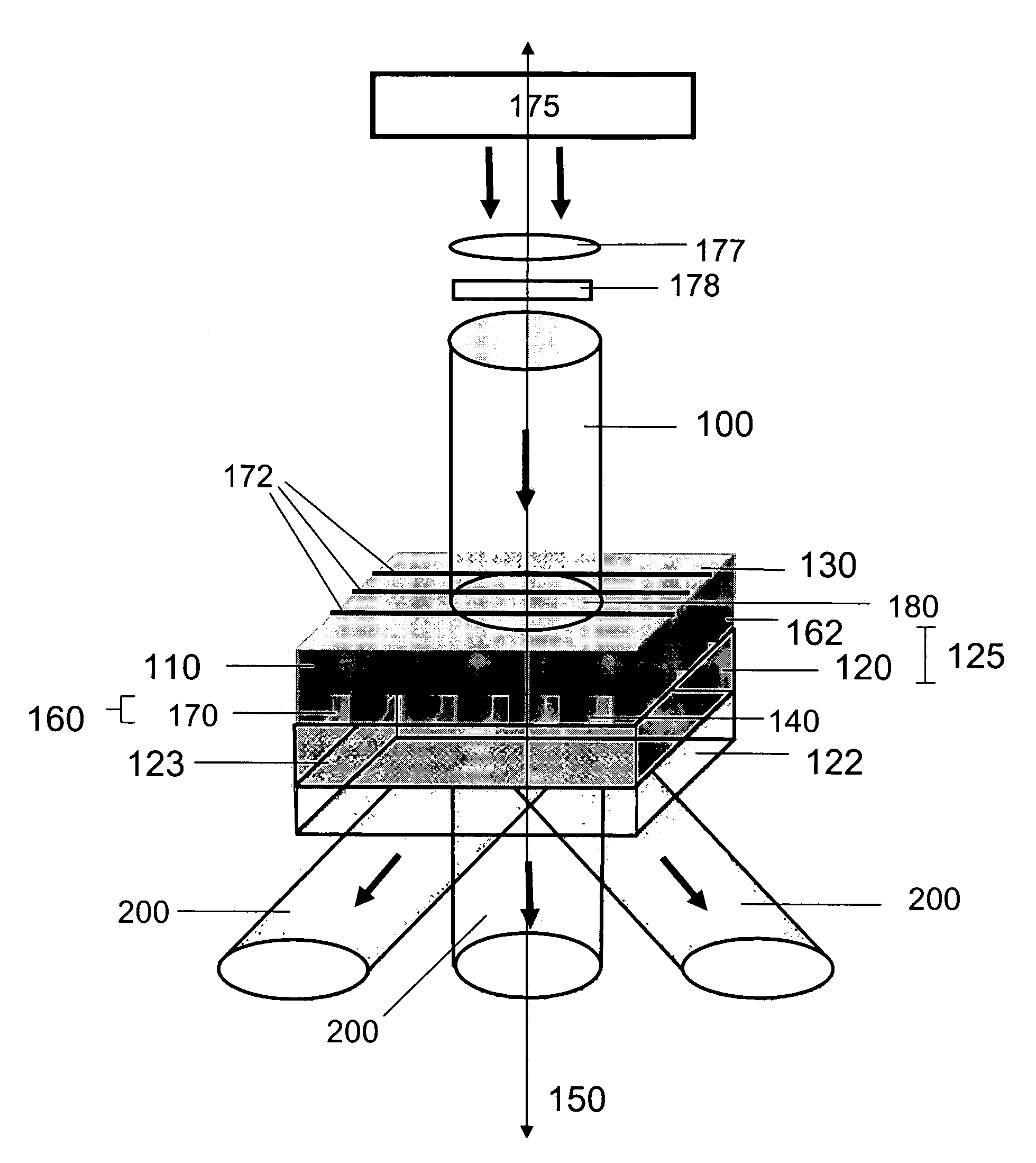
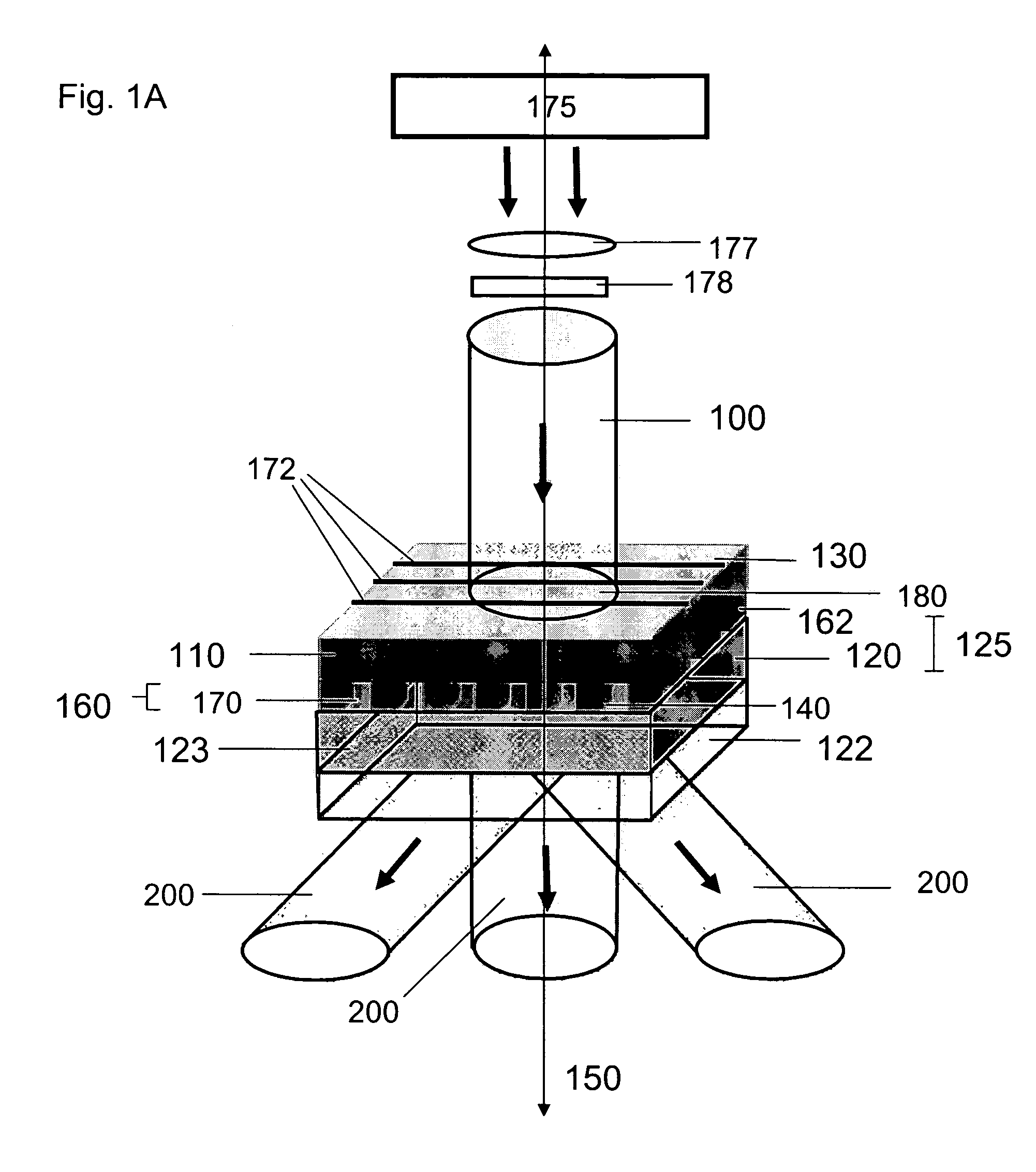
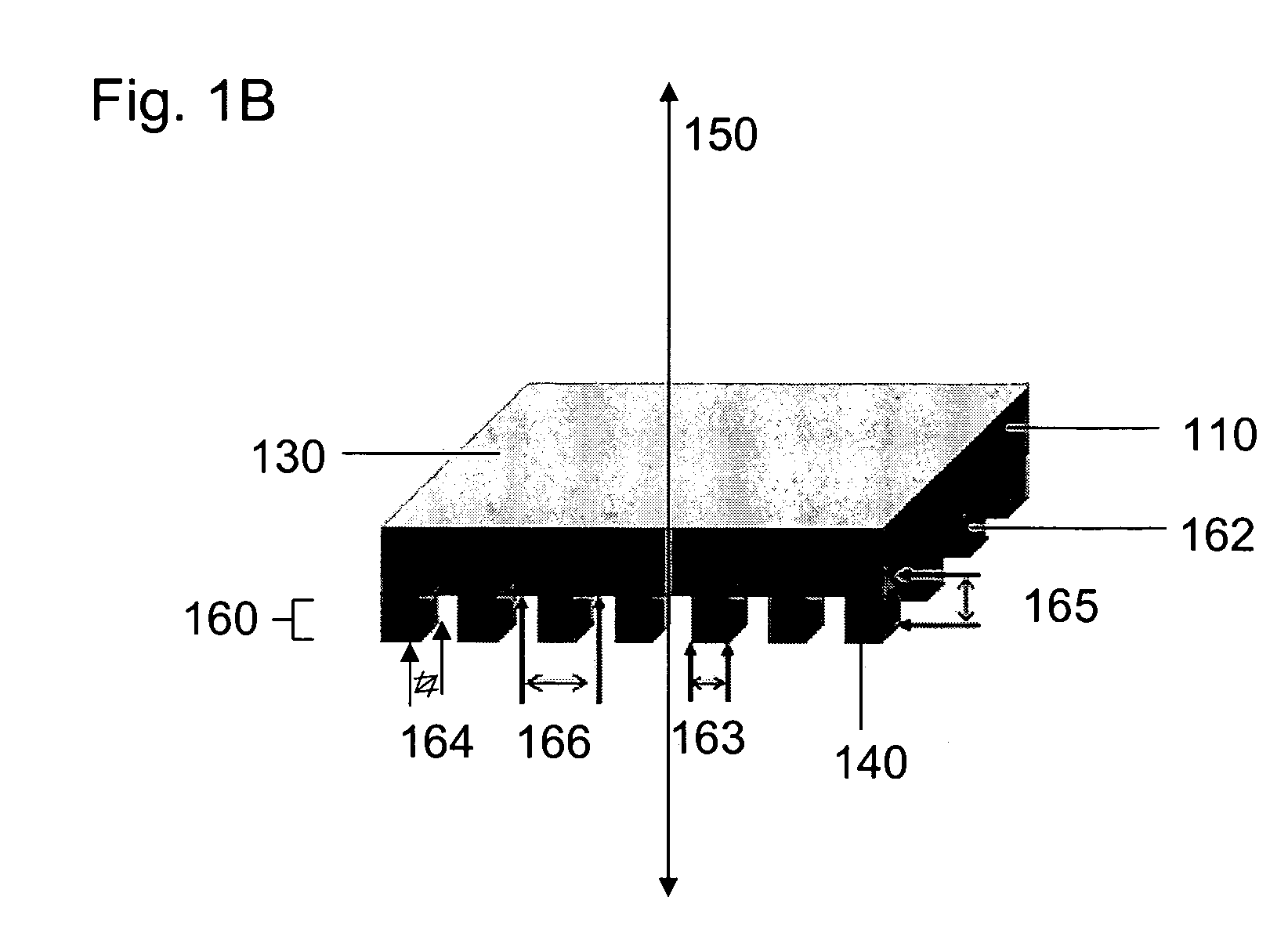
[0102]The practical utility of 3D nanostructures depends critically on their mechanical robustness and the ability to integrate them within microsystems, nanosystems and / or larger scale components to produce functional devices. To evaluate the utility of nanostructures generated by the present methods and devices, a nanoporous filter was fabricated and integrated within a microfluidic channel in a microfluidic system. The ability of the methods and devices of the present invention to fabricate useful 3D nanostructures was verified by demonstrating good mechanical properties and filtering performance of the nanoporous filter constructed.

[0103]To illustrate these features, a 3D nanostructured filter element was fabricated comprising a plurality of 3D nanostructures and integrated into a channel of a microfluidic system for separating sub-micron particles from fluid flows. The conformable phase mask employed in th...

example 2

Modeling calculations of the Intensity Distributions and Nanostructures Generated by Phase Masks of the Present Invention

[0108]FIG. 7A-L present scanning electron micrographs and modeling results (see inserts) for a broad range of periodic structures that can be fabricated over large areas using the methods of the present invention. These methods are high versatile and may be used with a variety of phase mask types, optical configurations and light sources, such as visible and ultraviolet lasers as well as filtered mercury lamps. Rigorous coupled wave analysis defines the computed distributions of intensity in each case, as illustrated in the insets, except for frames 7H, 7I and 7J, which were determined using Fraunhofer analysis to avoid the excessive computational requirements of Rigorous coupled wave analysis for these cases. A quantitative analysis of the modeling results and scanning electron micrographs indicates good agreement between computed distributions of intensity and t...

example 3

Selective Variation of Spatial and Temporal Coherence of Electromagnetic Radiation Used in the Present Methods

[0117]In embodiments of the present invention useful for a number of fabrication applications, the spatial coherence and / or temporal coherence of the electromagnetic radiation used in the present methods is selectively adjusted to control important structural characteristics of 3D structures fabricated, such as the region of a 3D structure in which nanoscale and / or microscale features are localized. Control provided by selective variation of spatial and / or temporal coherence is used in these methods of the present invention to optimize selected structural characteristics for a diverse range of applications, device configurations and device environments.

[0118]In one embodiment, the temporal coherence and / or spatial coherence of electromagnetic radiation directed onto a mask element in optical communication with a radiation sensitive material is selected to prepare 3D structur...


PUM

PropertyMeasurementUnit
heightsaaaaaaaaaa
thicknessesaaaaaaaaaa
thicknessaaaaaaaaaa

Abstract

The present invention provides methods and devices for fabricating 3D structures and patterns of 3D structures on substrate surfaces, including symmetrical and asymmetrical patterns of 3D structures. Methods of the present invention provide a means of fabricating 3D structures having accurately selected physical dimensions, including lateral and vertical dimensions ranging from 10s of nanometers to 1000s of nanometers. In one aspect, methods are provided using a mask element comprising a conformable, elastomeric phase mask capable of establishing conformal contact with a radiation sensitive material undergoing photoprocessing. In another aspect, the temporal and / or spatial coherence of electromagnetic radiation using for photoprocessing is selected to fabricate complex structures having nanoscale features that do not extend entirely through the thickness of the structure fabricated.

Description

CROSS-REFERENCE TO RELATED APPLICATIONS[0001]This application claims priority under 35 U.S.C. 119(e) to U.S. provisional Patent Applications 60 / 526,245 and 60 / 598,404 filed Dec. 1, 2003 and Aug. 2, 2004, respectively, which are hereby incorporated by reference in their entireties to the extent not inconsistent with the disclosure herein.STATEMENT REGARDING FEDERALLY SPONSORED RESEARCH OR DEVELOPMENT[0002]This invention was made with Government support under Contract Number DEFG02-91ER45439 awarded by the Department of Energy (DOE). The Government has certain rights in the invention.BACKGROUND OF INVENTION[0003]Advances in nanoscience and technology increasingly rely on techniques for fabricating structures comprising features having selected physical dimensions, such as lengths, heights and widths, in the nanometer regime. Methods that have emerged from the microelectronics industry, such as deep UV projection mode lithography and electron beam lithography, are well suited for patte...

Claims


Application Information

Patent Timeline
Patent Type & Authority Patents(United States)
IPC IPC(8): G03F7/00B81C99/00B82BB82B3/00G03F1/00G03F1/60G03F7/20
CPCB82B3/00B82Y10/00B82Y30/00B82Y40/00G03F7/70408G03F1/60G03F7/70283G03F7/703G03F7/7035G03F1/14G03F1/50Y10S430/146G03F7/00G03F7/20G03F7/26B81C99/00
Inventor ROGERS, JOHN A.JEON, SEOKWOOPARK, JANGUNG
Owner THE BOARD OF TRUSTEES OF THE UNIV OF ILLINOIS
Why Eureka
Try Eureka