
Pressure equalizer in thrust chamber electrical submersible pump assembly having dual pressure barriers

a technology of electrical submersible pumps and equalizers, which is applied in the direction of piston pumps, positive displacement liquid engines, borehole/well accessories, etc., and can solve the problems of destroying equipment, temperature rise, and overflowing the volume capacity of motors

Inactive Publication Date: 2010-05-04
BAKER HUGHES HLDG LLC
View PDF10 Cites 30 Cited by
  • Summary
  • Abstract
  • Description
  • Claims
  • Application Information

AI Technical Summary

Problems solved by technology

Also, heat of the motor during operation causes the temperature to rise.
The expansion of the oil could exceed the volume capacity of the motor, causing a leak.
One problem with existing seal sections is that if a leak occurs, well fluid will enter the motor and cause an electrical short, thus destroying the equipment.
Redundant seal sections are costly, however, and only add an additional amount of time before failure eventually occurs.
Often, if the top seal section fails, vibration and leakage will also cause failure out of the other seal sections in fairly short order.

Method used


Image

  • Pressure equalizer in thrust chamber electrical submersible pump assembly having dual pressure barriers
  • Pressure equalizer in thrust chamber electrical submersible pump assembly having dual pressure barriers
  • Pressure equalizer in thrust chamber electrical submersible pump assembly having dual pressure barriers

Examples


Embodiment Construction

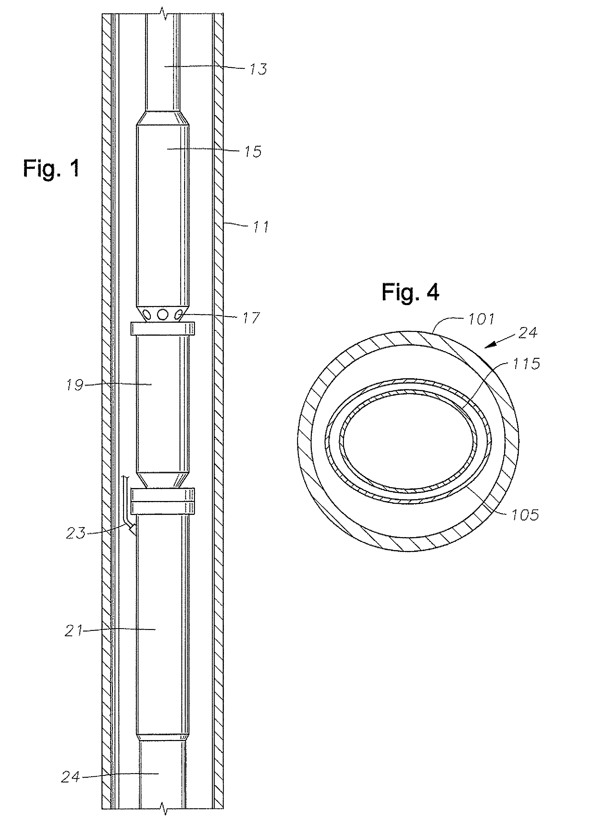
[0014]Referring to FIG. 1, a well is illustrated as having a casing 11. A string of production tubing 13 is lowered into casing 11. A rotary pump 15 is attached to the lower end of tubing 13 for delivering well fluid up tubing 13. Pump 15 is typically a centrifugal pump having a large number of stages, each stage having an impeller and a diffuser. Alternately, pump 15 can be other types, such as a progressive cavity pump. Pump 15 has an intake 17 that draws well fluid into pump 15.

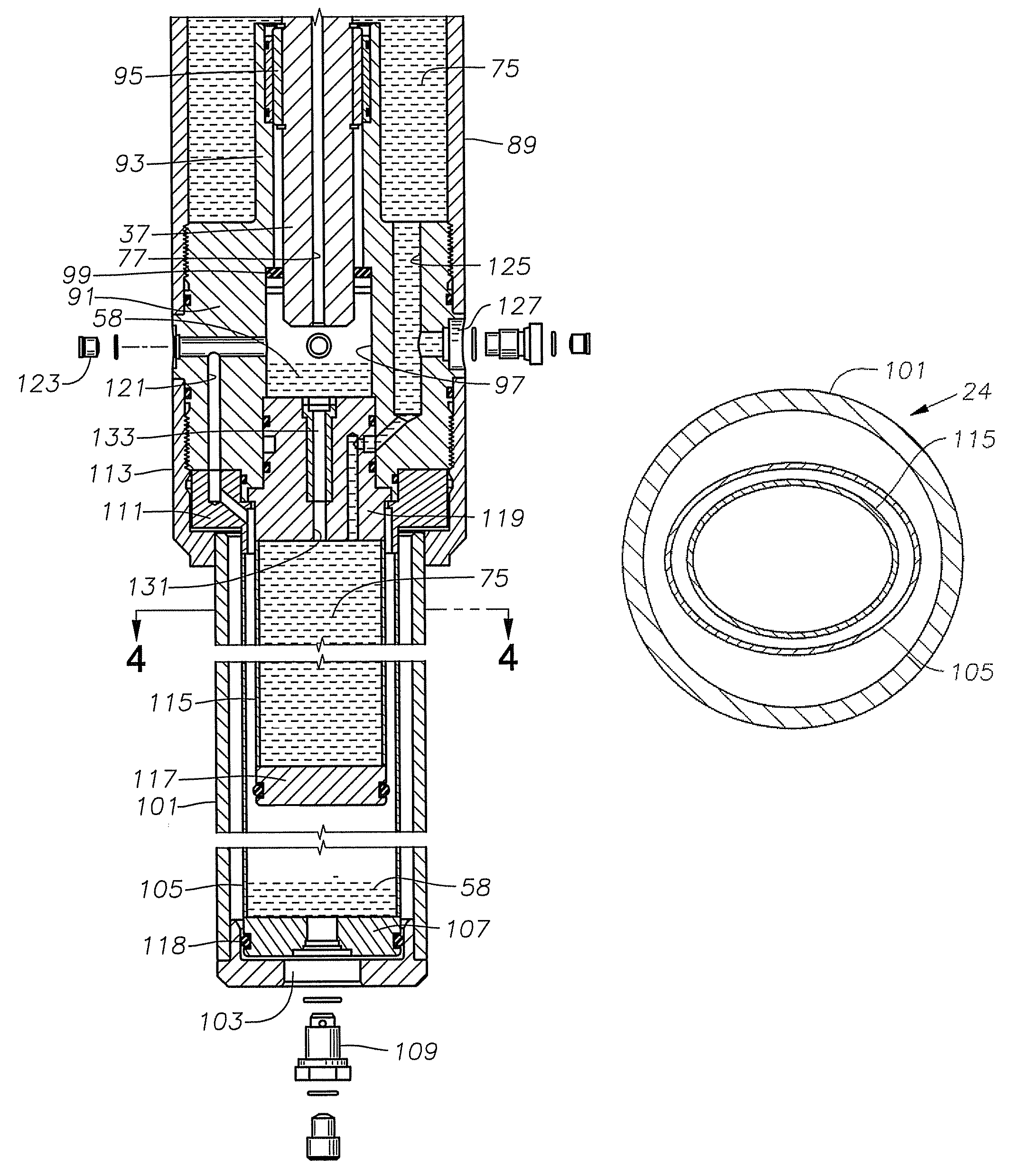
[0015]A thrust unit 19 is connected to the lower end of pump 15. An electrical motor 21 is secured to the lower end of thrust unit 19. Motor 21 is normally a three-phase electrical motor supplied with power from a power cable 23 extending down from the surface. A pressure equalizing assembly 24 is secured to the lower end of motor 21.

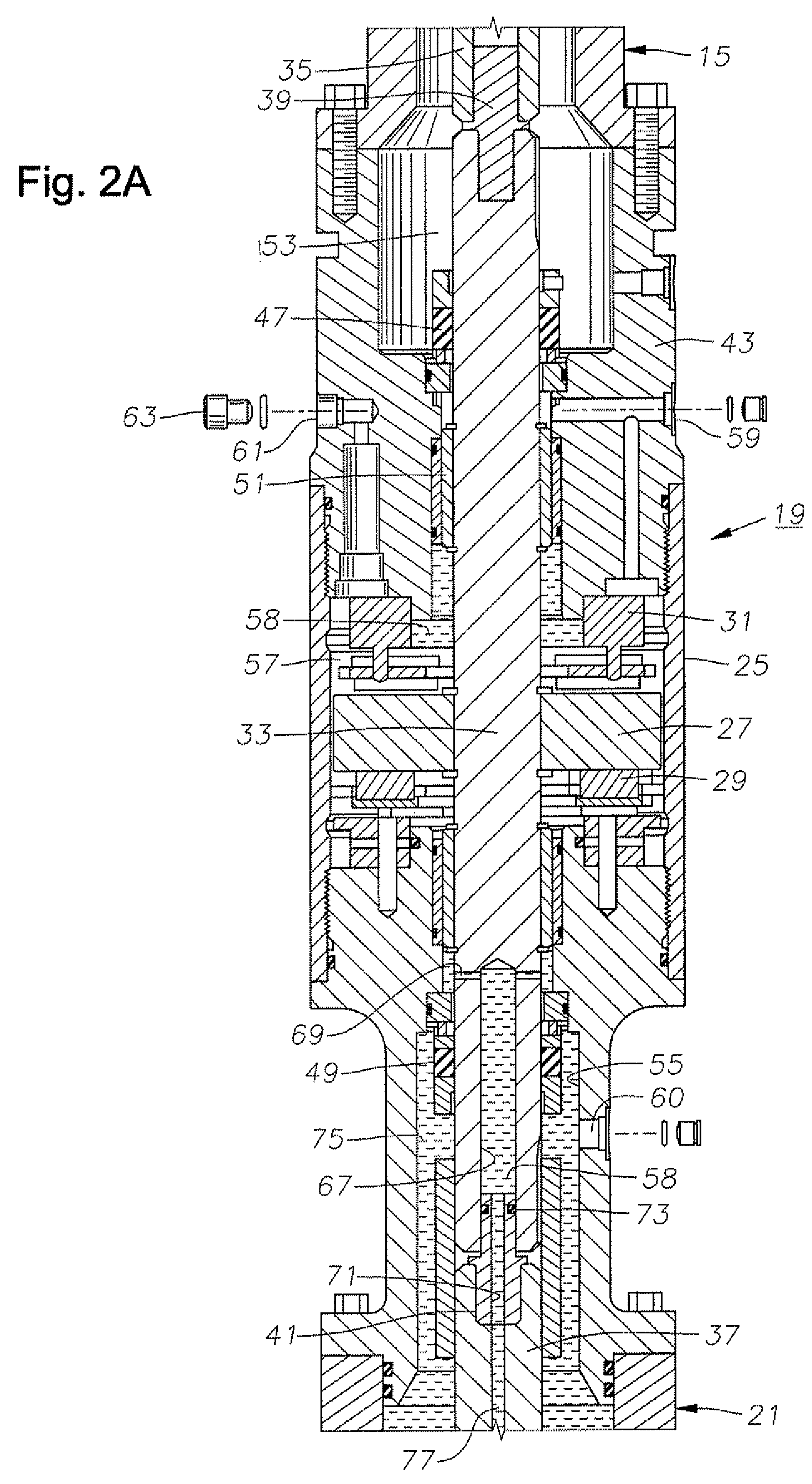
[0016]Referring to FIG. 2A, thrust unit 19 has a housing 25. A conventional thrust bearing assembly for absorbing thrust from pump 15 (FIG. 1) is contained within housing 25. ...


PUM


Abstract

A well pump assembly has a rotary pump with an electrical motor that contains a motor lubricant. A thrust chamber is mounted between the motor and the pump, the thrust chamber containing a thrust chamber lubricant. Seals prevent the entry of thrust chamber lubricant into the motor chamber. A pressure equalizing chamber is mounted to the motor for admitting well fluid. A first pressure barrier in the equalizing chamber equalizes the pressure of the thrust chamber lubricant with that of the well fluid. A second pressure barrier contained within the first pressure barrier equalizes the pressure of the motor lubricant with thrust chamber lubricant.

Description

FIELD OF THE INVENTION[0001]This invention relates in general to submersible well pump assemblies, and in particular to a pressure equalizer that reduces the pressure differential between lubricant in the motor and the exterior hydrostatic pressure in the well bore.BACKGROUND OF THE INVENTION[0002]Electrical submersible pumps are used to convey large volumes of fluid from wells typically for hydrocarbon production. Normally an electrical submersible pump assembly will comprise a rotary pump and a downhole electrical motor. The rotary pump may be a centrifugal pump made up of a large number of centrifugal stages of impellers and diffusers. Alternately, a progressing cavity pump may be utilized in some circumstances.[0003]The motor is filled with a dielectric motor oil or lubricant. The motor oil expands when the temperature rises, which normally occurs when lowering a pump into a well. Also, heat of the motor during operation causes the temperature to rise. The expansion of the oil c...

Claims


Application Information

Patent Timeline
Patent Type & Authority Patents(United States)
IPC IPC(8): F04B35/04
CPCF04D29/051E21B43/128F04D29/0413F04B35/04
Inventor PARMETER, LARRY J.PORETTI, ARTURO LUIS
Owner BAKER HUGHES HLDG LLC
Learn More