Float bath bottom refractory brick and process for its production

a refractory brick and bottom technology, applied in the field of refractory bricks, can solve the problems of inhibiting smooth production of plate glass, and achieve the effects of prolonging the life of the float bath, suppressing flaking phenomena, and suppressing nepheline formation

Inactive Publication Date: 2010-05-04
AGC INC
View PDF19 Cites 3 Cited by
  • Summary
  • Abstract
  • Description
  • Claims
  • Application Information

AI Technical Summary

Benefits of technology

[0021]The float bath bottom refractory brick to be produced by the present invention has a glass phase rich in K2O. Therefore, infiltration of Na2O from the surface of the refractory brick into the inside via the tin bath can be suppressed, whereby formation of Nepheline can be suppressed. Further, the glass phase absorbs volume expansion of the formed Nepheline metamorphic phase and suppresses flaking phenomena. Accordingly, the life of a float bath employing the float bath bottom refractory brick can be prolonged. Further, in a process for producing plate glass employing the float bath, defects (scars) of glass accompanying the flaking phenomena can be reduced, whereby improvement in quality and rate of non-defective products will be achieved.

Problems solved by technology

The flakes, which have a specific gravity smaller than that of the molten tin, float up in the tin bath and scar the glass or generate foreign matters, and they can be a major cause of inhibiting smooth production of plate glass.

Method used


Image

  • Float bath bottom refractory brick and process for its production
  • Float bath bottom refractory brick and process for its production
  • Float bath bottom refractory brick and process for its production

Examples


example 1

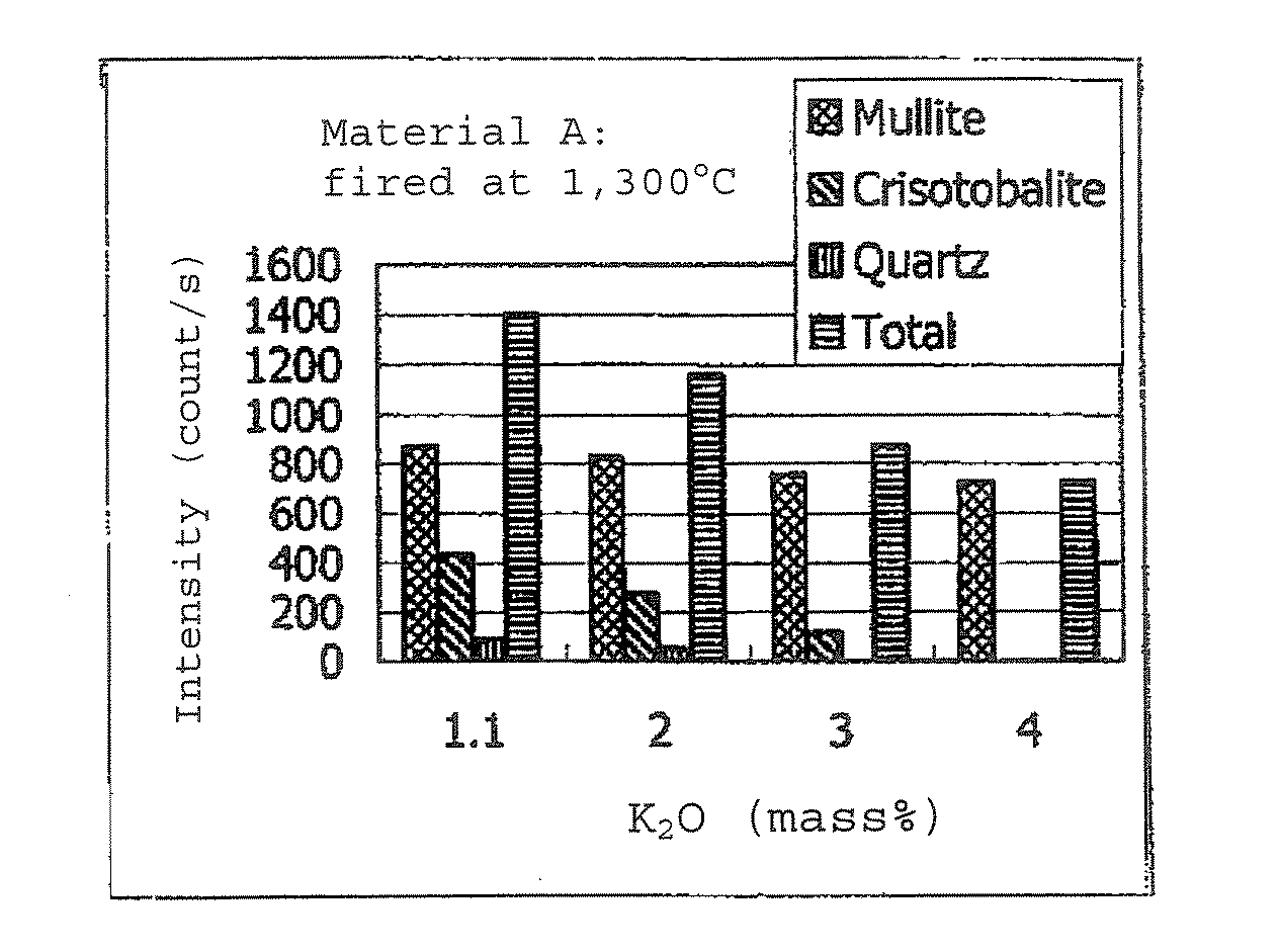
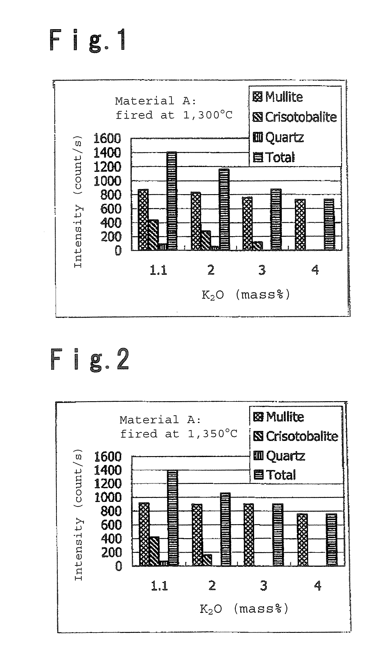
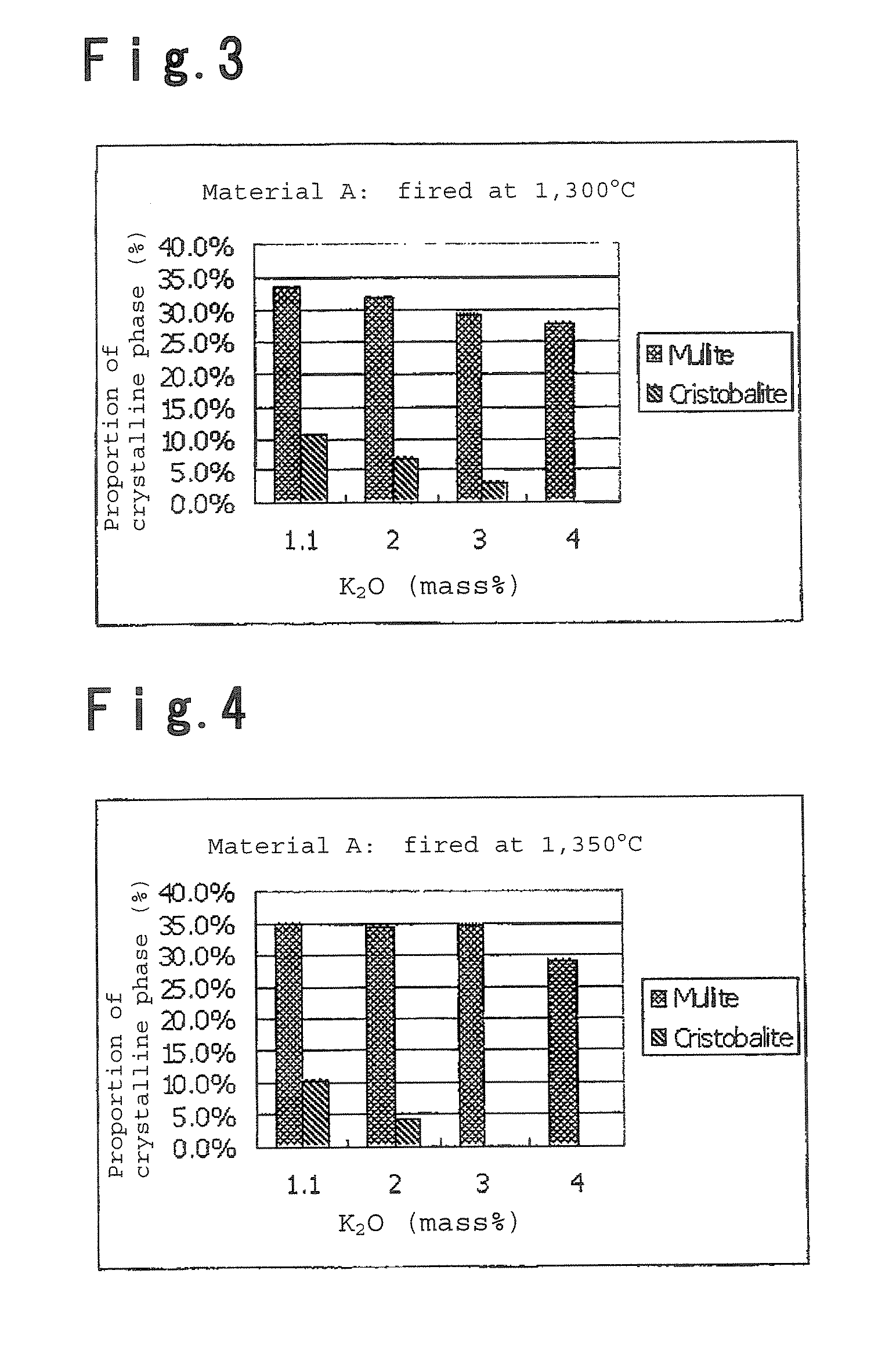
[0051]To 10 g of the clayey material A, potassium carbonate as a K2O source was added in an amount of not added (1.1%), 2, 3 or 4% as calculated as K2O mass % after mixing. The material having no potassium carbonate added corresponds to sample 1 (Comparative Example 1), and mixtures having potassium carbonate added in an amount of 2%, 3% and 4% correspond to sample 2 (Example 1), sample 3 (Example 1) and sample 4 (Example 1), respectively. As potassium carbonate, one preliminarily pulverized in a mortar was employed. Kneading was carried out in a mortar. The kneaded product was put in a mold, and molded into pellets by means of a pressing machine. The molded product was fired at 1,300° C. for 24 hours.

[0052]The fired product was crushed into granules, and the obtained granular refractory material was kneaded, molded into two molded products with a shape of a desired float bath bottom refractory brick, and the two molded products were dried and fired at 1,300° C. and 1,350° C., respe...

example 2

[0057]In the same manner as in Example 1, to 10 g of the clayey material B, potassium carbonate as a K2O source was added in an amount of 0.3 (not added), 2, 3, 4 or 6% as calculated as K2O mass % after mixing. The material having no potassium carbonate added corresponds to sample 5 (Comparative Example 2), and mixtures having potassium carbonate added in an amount of 2%, 3%, 4% and 6% correspond to sample 6 (Example 2), sample 7 (Example 2), sample 8 (Example 2) and sample 9 (Comparative Example 3), respectively. As potassium carbonate, one preliminarily pulverized in a mortar was employed. Kneading was carried out in a mortar. The kneaded product was put in a mold and molded into pellets by means of a pressing machine. The molded product was fired at 1,300° C. for 24 hours.

[0058]The fired product was crushed into granules, and the obtained granular refractory material was kneaded and molded into two molded products with a shape of a desired float bath bottom refractory brick, and ...


PUM

PropertyMeasurementUnit
grain sizeaaaaaaaaaa

Abstract

A process for producing a float bath bottom refractory brick which can suppress a reaction with Na2O from glass at the surface of the refractory brick and thereby prevent flaking phenomena, which process comprises adding a potassium compound to a clayey material comprising from 30 to 45 mass % of Al2O3 and from 50 to 65 mass % of SiO2 and having a Na2O content of at most 1 mass %, so that the K2O content in the float bath bottom refractory brick to be produced would be from 2 to 4 mass %; and a refractory brick useful for a float bath bottom for production of plate glass by a float process.

Description

TECHNICAL FIELD[0001]The present invention relates to a refractory brick to be used for the bottom of a float bath i.e. a tin bath in float process for production of plate glass, and a process for its production.BACKGROUND ART[0002]In production of plate glass by float process, a float bath on which molten glass is discharged from a glass melting furnace and formed into a ribbon, comprises a metal casing lined with a refractory brick, and is filled with molten tin. Glass molten in the melting furnace is discharged on the surface of the tin bath, flows on the tin bath and advances to be formed into smooth plate glass. As usual plate glass (soda lime glass) for buildings, automobiles, etc., glass containing about 15 mass % of Na2O is used. Such glass is in contact with the molten tin at its bottom surface, and at the interface, Na2O in the glass diffuses into the tin bath. As a bottom refractory brick for such a float bath, Chamotte brick containing Al2O3 and SiO2 as the main componen...

Claims


Application Information

Patent Timeline
Patent Type & Authority Patents(United States)
IPC IPC(8): C04B35/18
CPCC04B33/04C04B35/185C03B18/16C04B2235/3201C04B2235/3418C04B2235/5427C04B2235/5436C04B2235/72C04B2235/77C04B2235/80C04B2235/96C04B2235/9669C04B2235/5463Y02P40/57
Inventor KABASHIMA, SHUJISAKAI, KOUZOUYOKOTANI, MASAMICHI
Owner AGC INC
Why Eureka
Try Eureka