
Reversing auger system

a technology of reverse auger and hopper, which is applied in the direction of lighting and heating equipment, applications, instruments, etc., can solve the problems of reducing slowing down the time period required for the system to complete, and the temperature of the beverage mixture can be reduced, so as to improve the chilled beverage production apparatus and reduce the temperature of the beverage mixture

Active Publication Date: 2010-05-11
BUNN O MATIC
View PDF14 Cites 34 Cited by
  • Summary
  • Abstract
  • Description
  • Claims
  • Application Information

AI Technical Summary

Benefits of technology

[0002]The present disclosure relates to an improved apparatus for producing a chilled or partially frozen beverage often referred to as a slush beverage. A variety of apparatus have been designed to produce chilled beverages as well as to produce beverages which are in slush form. Some of these apparatus are referred to as “granita” machines. Such apparatus can be used to produce slush beverages for a number of products including fruit juices, coffee-based beverages, tea-based beverages, dairy based beverages, as well as beverages containing alcohol. The apparatus include a chilling structure and some form of blade or auger which moves relative to the chilling portion to strip the frozen product off and circulate the beverage along the chilling portion. Circulation of the frozen beverage within the beverage hopper and along the chilling portion helps to reduce the temperature of the beverage mixture thereby causing the partially frozen beverage to approach a slush consistency. There is a need for an improved chilled beverage producing apparatus.
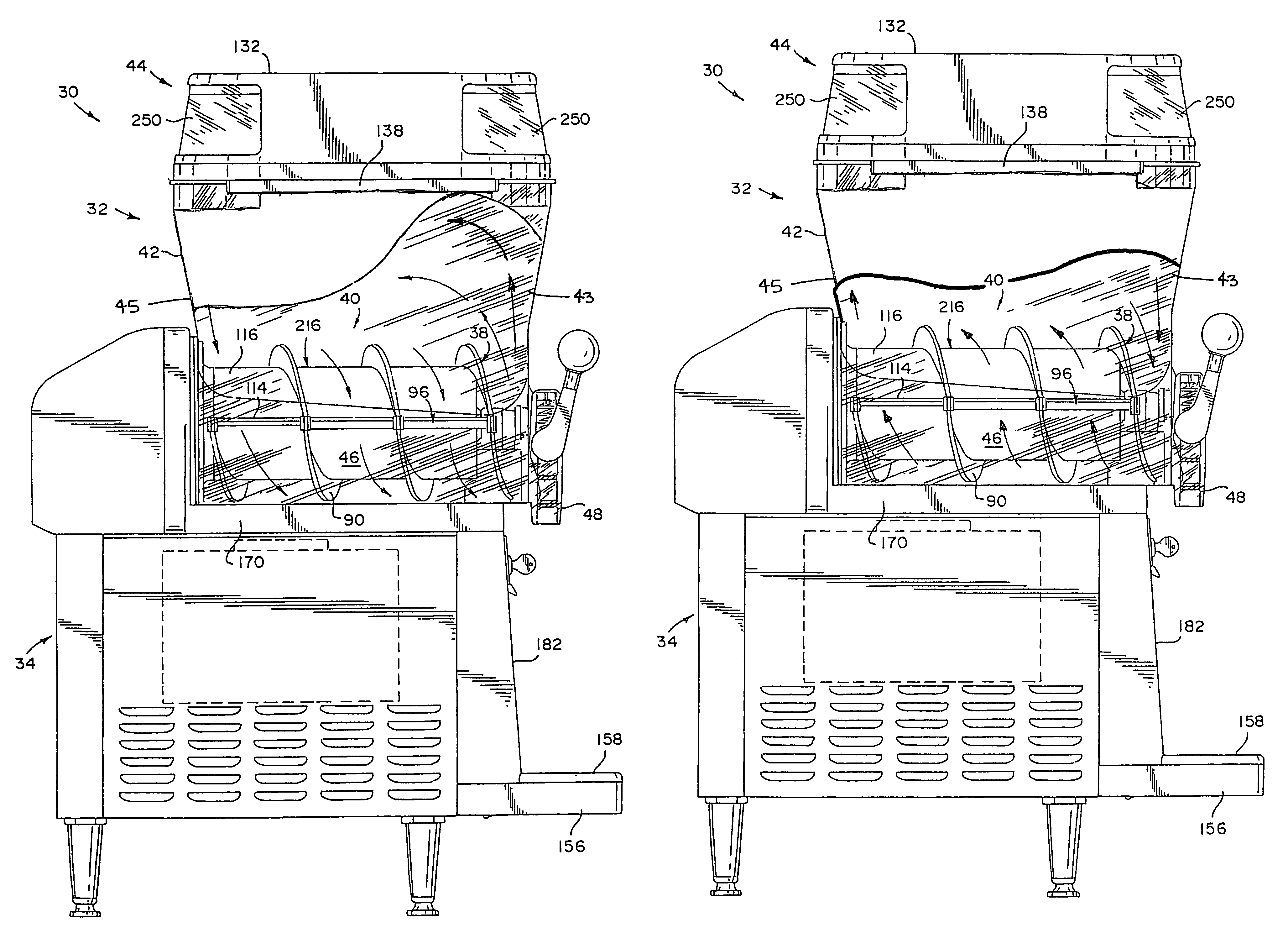
[0004]A “freeze down” event is defined for purposes of this application as the time period required to chill and mix a quantity of warmed liquid beverage within the beverage hopper until a partially frozen beverage of adequate serving quality can be dispensed. A “freeze down” events typically occurs either after (a) the machine is partially re-filled with beverage products during periods of heavy use, (b) it is reactivated from a “night mode” operation, or (c) the initial filling of the beverage hopper after cleaning. As the ice crystals are scraped off the chilling structure, they rise in the beverage hopper since the crystals are less dense than the warmed beverage in the lower portion of the hopper. At the same time those ice crystals are rising due to their buoyancy, they are also being pushed forward and upward by the action of the auger. In prior devices, the “ice hump” would typically break up after it becomes large enough to collapse under its own weight and to fall back into the lower portion of the container. This collapse can take a considerable period of time to occur. As a result, the formation of an “ice hump” substantially slows the time period required for the system to complete a “freeze down” event.
[0006]One prior attempt to deal with the problems of delayed freeze down and insufficient product mixing has been to provide a second auger or mixing mechanism for breaking up the “ice hump” or stagnant corners within the beverage. This approach has the drawback of increasing the cost of the frozen beverage machines, their complexity, as well as creating difficulties in servicing them. Such two auger machines also have a tendency to mix air into the partially frozen beverage which causes undesirable “frothing” of the product. It is one object of the invention to provide a cost efficient partially frozen beverage machine having an improved mixing apparatus and method for providing a more consistent frozen beverage product.
[0007]It is another object of the invention to provide an improved mixing apparatus and method of using same that substantially prevents the formation of an “ice hump” or rapidly breaks up any “ice hump” that begins to form thereby providing rapid completion of a “freeze down” event.
[0008]The present disclosure is directed to an improved apparatus for producing a partially frozen beverage which includes a beverage hopper for retaining a quantity of partially frozen beverage, a rotatable mixing member, a chilling unit for cooling the beverage within the hopper, a sensing member for detecting the occurrence of a rotation reversal condition, a controller for generating a rotation reversal signal, and a drive motor operably coupled to the rotatable mixing member for rotating the mixing member in a first direction during normal operation and in a second, reverse direction in response to a rotation reversal signal. The reverse rotation of the rotatable mixing member improves the efficiency of the mixing of partially frozen beverage within the beverage hopper and is effective in speeding the conclusion of a “freeze down” event relative to prior “forward rotation only” beverage apparatus. Further, the machines disclosed may be designed with a single mixing member, rather than the more costly multiple mixing member machines sometimes used with prior machines.
[0009]In one preferred embodiment of the present invention, the sensing member is programmed to detect a “freeze down” event of a certain duration as a rotation reversal condition. During this operation, the chilling unit is maintained below a pre-determined temperature for periods of greater than about ten (10) minutes. Such operation conditions are likely to produce an “ice hump.” Reversal of the rotatable member prevents or limits this occurrence by pulling ice crystals from the top-front portion of the machine and mixing them with the contents of the remainder of the beverage hopper. This causes more rapid “freeze down” of the beverage as complete mixing does not require waiting for collapse of the “ice hump” under its own weight. Where all or large portions of the beverage product is in liquid rather than partially frozen form, it may be necessary to cycle between forward rotation and reverse rotation repeatedly during a “freeze down” event. Preferably a torque sensor is also provided to sense the torque at the drive shaft of the drive motor. The torque sensor detects a torque valve that is correlated with a high quality product consistency. Once the selected torque value is detected, the flow of coolant into the chilling unit associated with beverage hopper is switched to an “off / ice” position. During the reverse rotation phase, the torque sensor is preferably deactivated so that it does not interfere with the operation of apparatus because reverse rotation may cause temporary fluctuations in measured torque which are not indicative of product quality.

Problems solved by technology

One problem with the prior frozen beverage apparatus is that the rotatable augers of such machines typically induce an “ice hump” condition within the beverage hopper in which frozen beverage product collecting at the top of the hopper toward its front end.
This collapse can take a considerable period of time to occur.
As a result, the formation of an “ice hump” substantially slows the time period required for the system to complete a “freeze down” event.
Another problem that arises is that the chilled beverage product can become less uniformly mixed within the beverage hopper than is desirable.
This can cause inconsistencies in the frozen beverage product from serving to serving.
Lack of uniform mixing with the prior rotatable augers is often due to stagnant areas forming within the beverage hopper which are not homogeneously mixed with the remainder of the frozen beverage.
Typically, these stagnant corners further contribute to inconsistencies in the beverage product.
This approach has the drawback of increasing the cost of the frozen beverage machines, their complexity, as well as creating difficulties in servicing them.
Such two auger machines also have a tendency to mix air into the partially frozen beverage which causes undesirable “frothing” of the product.
Such operation conditions are likely to produce an “ice hump.” Reversal of the rotatable member prevents or limits this occurrence by pulling ice crystals from the top-front portion of the machine and mixing them with the contents of the remainder of the beverage hopper.

Method used


Image

  • Reversing auger system
  • Reversing auger system
  • Reversing auger system

Examples


Embodiment Construction

[0019]While the present disclosure may be susceptible to embodiment in different forms, there is shown in the drawings, and herein will be described in detail, an embodiment with the understanding that the present description is to be considered an exemplification of the principles of the invention and is not intended to limit the invention to that as illustrated and described herein.

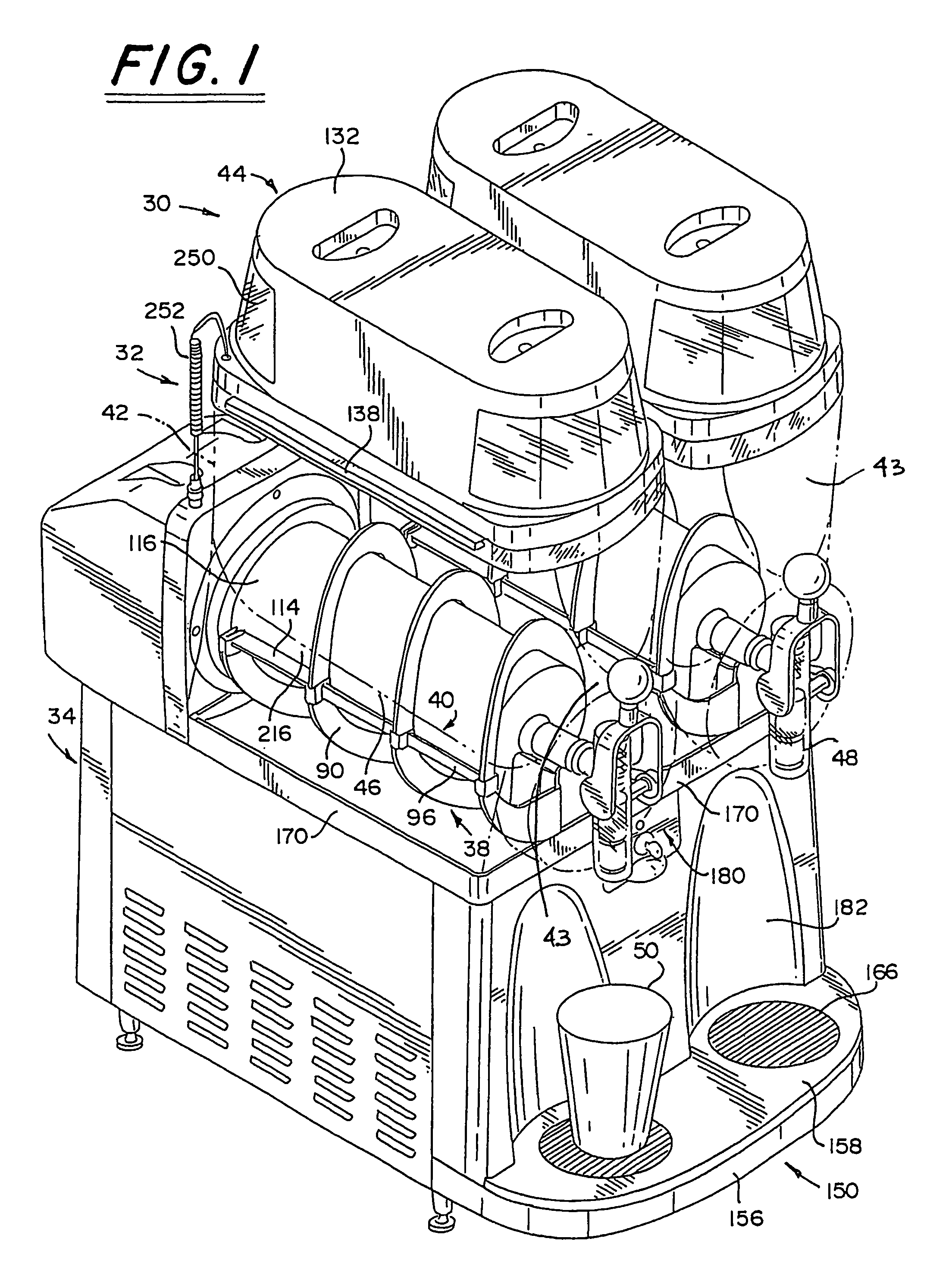
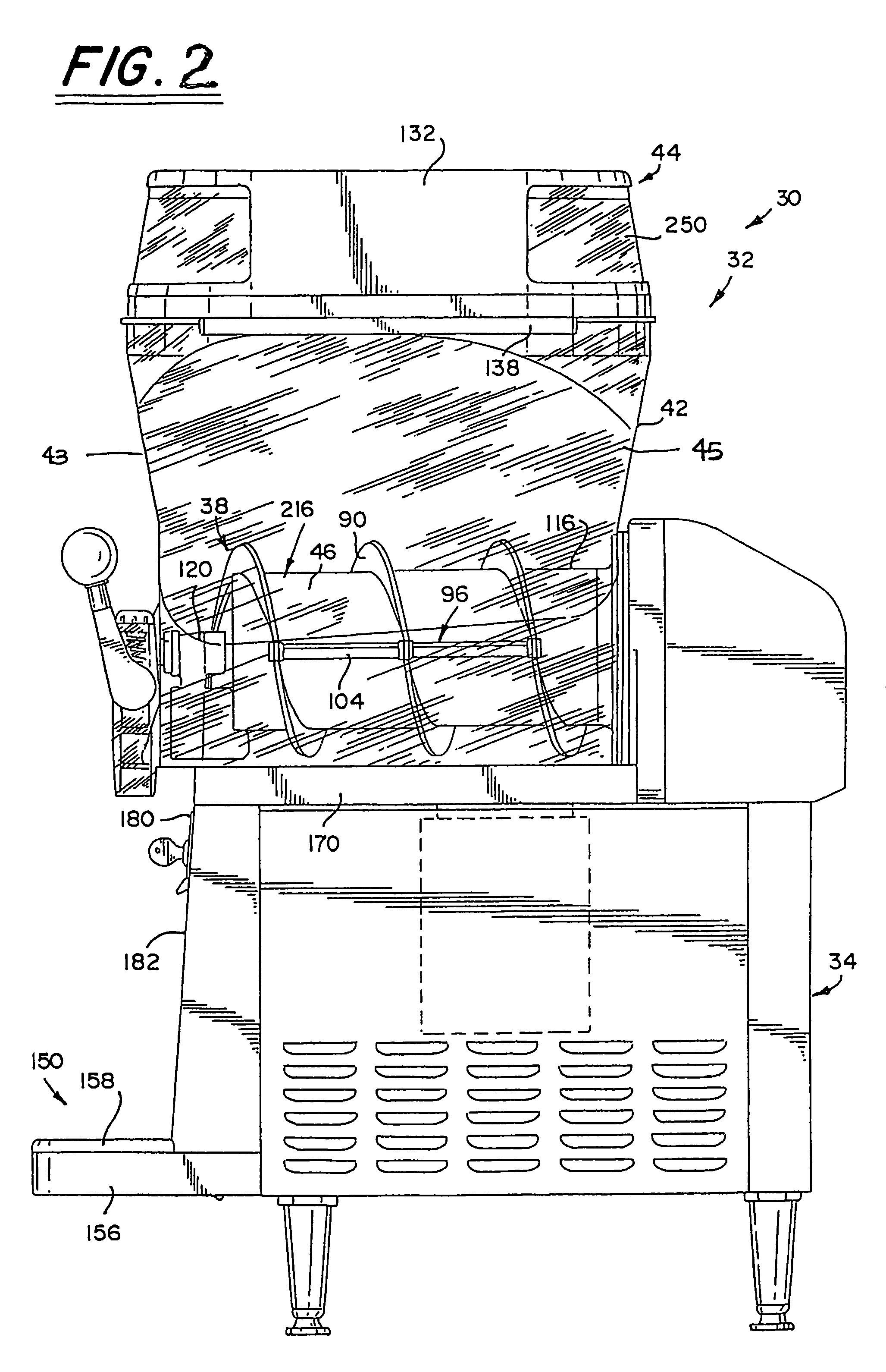
[0020]With reference to the figures, a chilled or slush beverage apparatus 30 is shown in perspective in FIG. 1. The beverage apparatus 30 includes at least one hopper assembly 32 which is retained on a housing 34. As will be described in greater detail hereinbelow, the housing 34 includes a drive motor 36 (see FIG. 5) and a coolant system 200 (see FIG. 6). The drive motor 36 as mentioned above drives a rotatable mixing member which in the preferred embodiment shown in FIG. 1-5 is an auger assembly 38. Auger assembly 38 is positioned proximate to a chiller assembly 40, both being retained within a corre...


PUM


Abstract

A method and apparatus for producing a chilled or partially frozen beverage is provided. The system includes a beverage hopper (32) a chilling unit (44), a rotatable mixing member (38), a sensing member (230) for detecting an occurrence of a rotation reversal condition, a controller for generating a rotation reversal signal in response to the sensing member, and a drive motor (36) coupled to the mixing member for rotating the mixing member in a first direction and a second, reverse direction in response to a rotation reverse signal.

Description

[0001]This Application is a U.S. Nationalization of PCT Application No. PCT / US03 / 09125, filed Mar. 25, 2003 and also claims the benefit of U.S. Provisional Patent Application No. 60 / 367,532, filed Mar. 25, 2002. The prior applications are expressly incorporated herein by reference in their entirety.BACKGROUND AND SUMMARY[0002]The present disclosure relates to an improved apparatus for producing a chilled or partially frozen beverage often referred to as a slush beverage. A variety of apparatus have been designed to produce chilled beverages as well as to produce beverages which are in slush form. Some of these apparatus are referred to as “granita” machines. Such apparatus can be used to produce slush beverages for a number of products including fruit juices, coffee-based beverages, tea-based beverages, dairy based beverages, as well as beverages containing alcohol. The apparatus include a chilling structure and some form of blade or auger which moves relative to the chilling portio...

Claims


Application Information

Patent Timeline
Patent Type & Authority Patents(United States)
IPC IPC(8): A23G9/12A23G9/04A23G9/22
CPCA23G9/045A23G9/228A23G9/12
Inventor KADYK, JEFFREY W.
Owner BUNN O MATIC
Learn More