Lost motion variable valve actuation system for engine braking and early exhaust opening

a technology of engine braking and valve actuation system, which is applied in the direction of valve details, valve arrangements, valve drives, etc., can solve the problems of unfavorable valve actuation, increased force required to open the exhaust valve, and reduced load on the exhaust valve opening mechanism used

Active Publication Date: 2010-05-11
JACOBS VEHICLE SYST
View PDF5 Cites 80 Cited by
  • Summary
  • Abstract
  • Description
  • Claims
  • Application Information

AI Technical Summary

Benefits of technology

[0066]Embodiments of the present invention may have many advantages, including providing variable engine braking, brake gas recirculation, and variable early exhaust valve opening for exhaust gas temperature control for emissions after-treatment and / or turbo stimulation for improved transient torque. Additional advantages may include a mechanically-driven exhaust main event for cold start and failsafe, meeting loading limits, especially cam Hertz stress, avoiding separation and impact loading between cams and rollers, avoiding valve bridge tilt, meeting exhaust valve seating velocity limits, and protecting against valve-piston contact.

Problems solved by technology

Increased exhaust back pressure, however, may undesirably increase the force required to open the exhaust valve for a compression-release event because the opening force applied to the exhaust valve must exceed the increased pressure in the engine cylinder resulting from the increased exhaust back pressure.
To some extent the increased exhaust back pressure may also increase the pressure applied to the back of the exhaust valve, which may counter-balance the increased pressure in the cylinder and thus reduce the loading on the exhaust valve opening mechanism used for the compression-release event.
There is a risk of valve-piston contact in many electronically-controlled variable valve actuation (VVA) systems.
For example, lost motion VVA systems that provide early valve opening and spill oil near peak lifts have an increased risk of valve piston contact if the spill does not function, which may occur, for example, due to a clogged spill port or a broken valve spring.

Method used


Image

  • Lost motion variable valve actuation system for engine braking and early exhaust opening
  • Lost motion variable valve actuation system for engine braking and early exhaust opening
  • Lost motion variable valve actuation system for engine braking and early exhaust opening

Examples


first embodiment

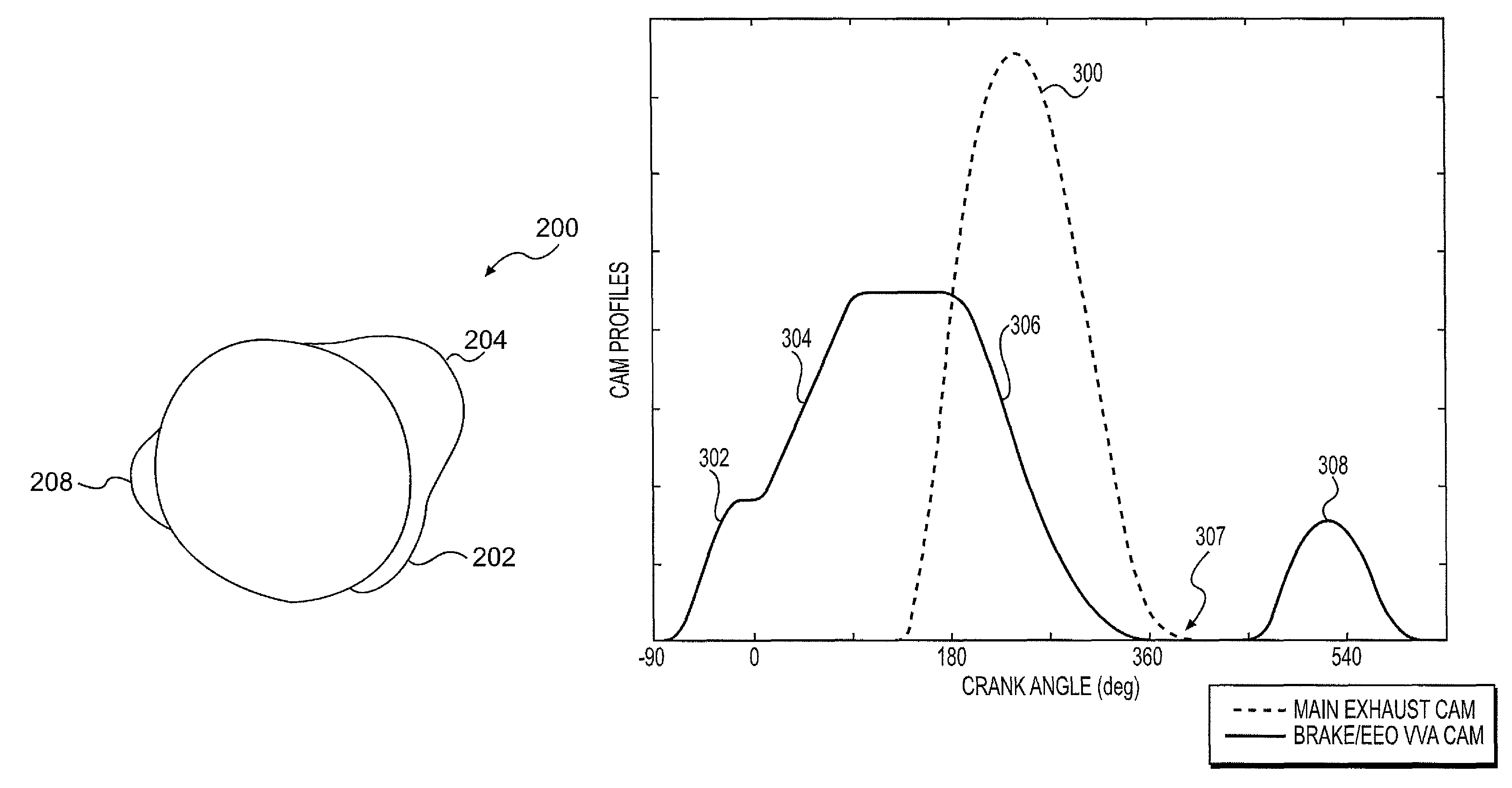
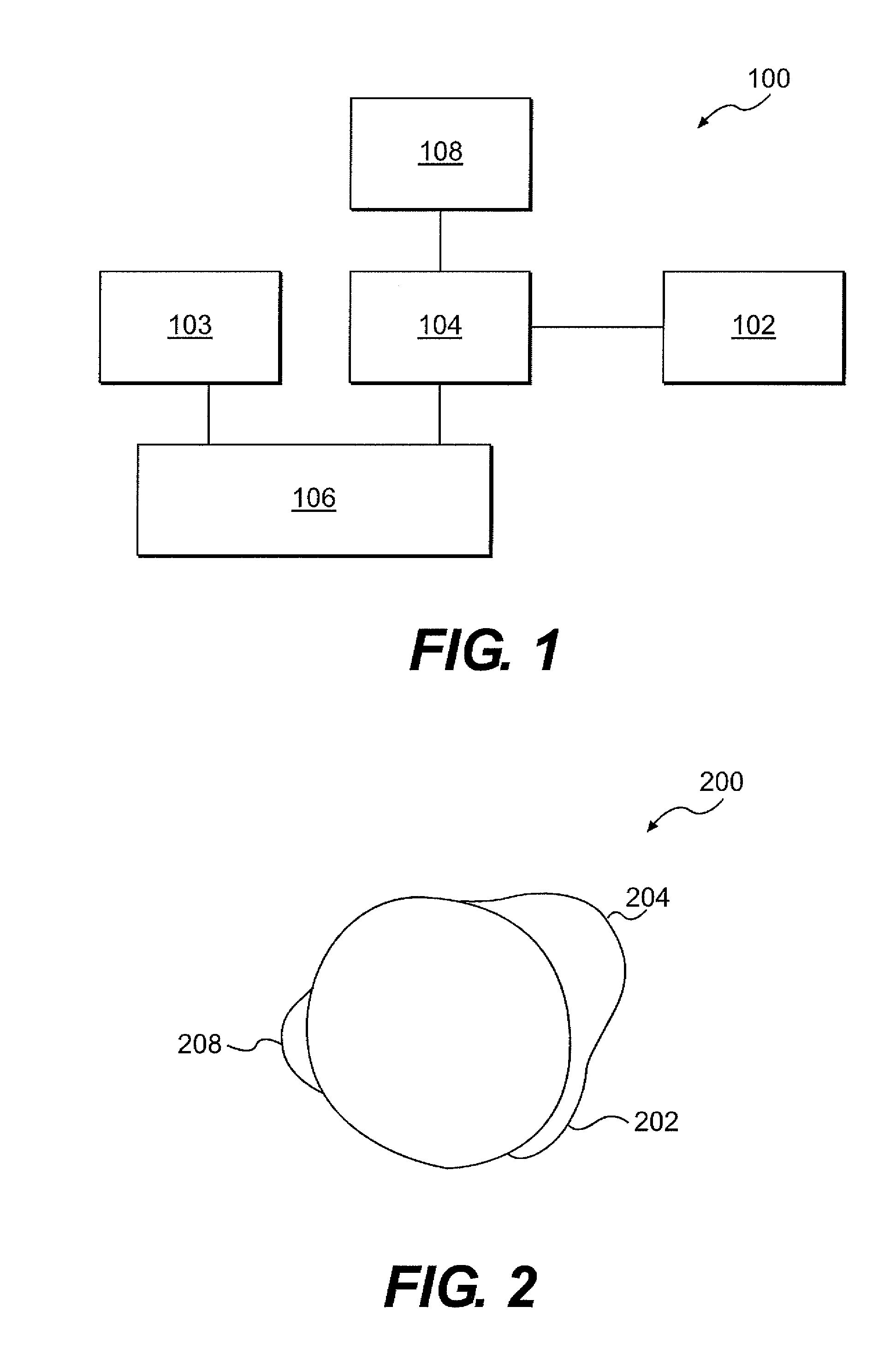
[0039]FIG. 1 is a block diagram that illustrates a valve actuation system 100 in accordance with the present invention. The valve actuation system 100 may include a first motion imparting means 102, such as a cam with one or more lobes or bumps, operatively contacting a lost motion system 104, which in turn may be operatively connected to one or more engine valves 106. The valve actuation system may further include a second motion imparting means 103 operatively connected to the one or more engine valves 106. It is appreciated that any number of valve train elements, such as push tubes, rocker arms, and or valve bridges may be provided between or as part of the first and second motion imparting means 102 and 103, the lost motion system 104, and the engine valves 106, without departing from the intended scope of the present invention. The first motion imparting means 102 may preferably include both a early exhaust valve opening lobe or bump, a compression release lobe or bump, and op...

second embodiment

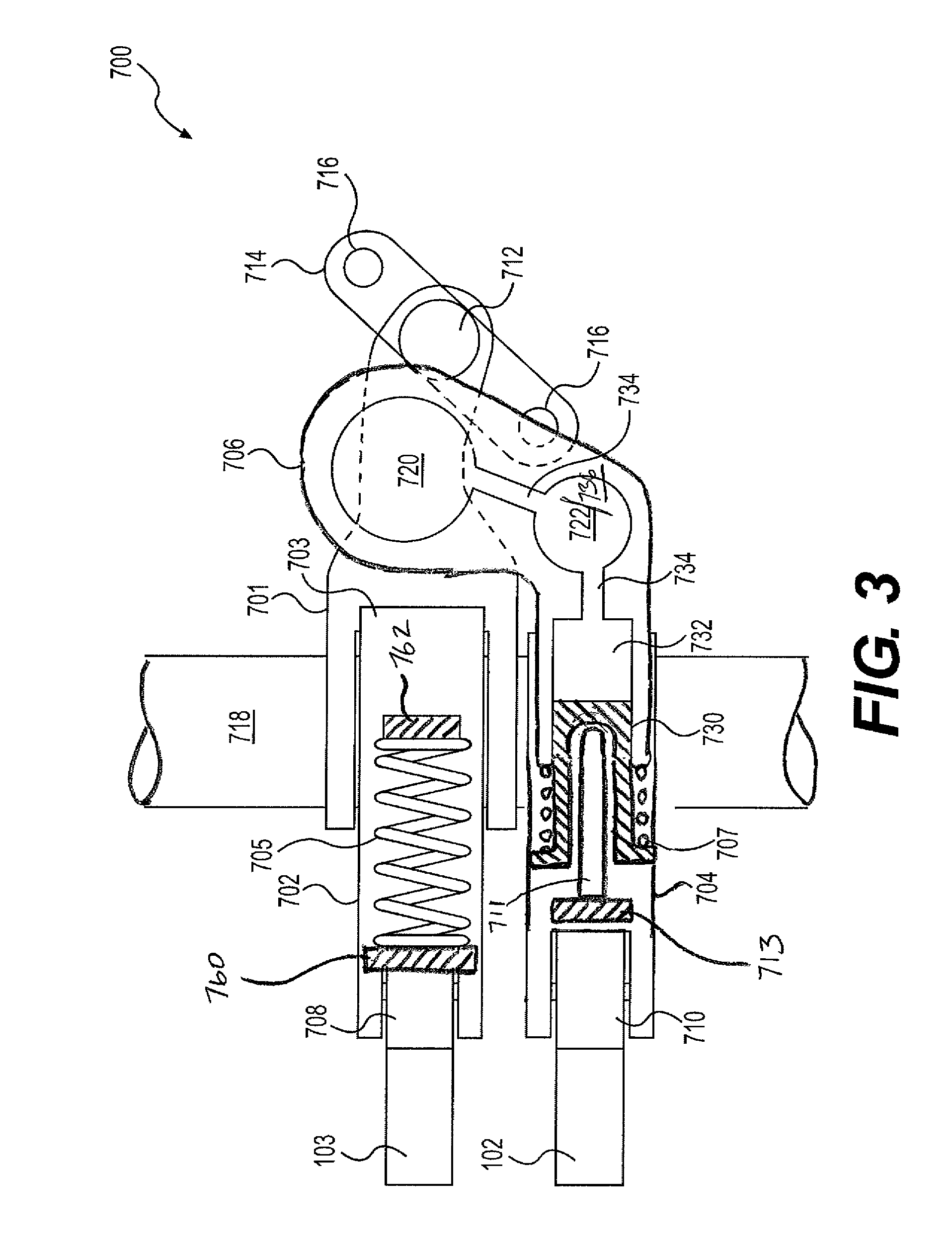
[0043]FIG. 3 is a schematic top view in partial cross section of variable valve actuation system 700 in accordance with the present invention. The variable valve actuation system 700 may include first and second valve train assemblies extending between the first and second motion imparting means, 102 and 103, respectively, and the exhaust valves 716. The first valve train assembly may include a first half (or main exhaust) rocker arm 701 pivotally mounted on a rocker shaft 718, and a second half rocker arm 702 pivotally mounted on the rocker shaft directly behind the first half rocker arm which together comprise an articulated rocker arm. The first half rocker arm 701 may include an elephant foot or other valve bridge contacting portion 712 adapted to apply a valve actuation motion to the engine valves, preferably exhaust valves, 716 through a valve bridge 714.

[0044]The second half rocker arm 702 may include a valve end portion 703 adapted to apply a pivoting motion to the first hal...

third embodiment

[0048]FIG. 6 is a schematic top view of a variable valve actuation system 700 in accordance with the present invention, in which like reference characters refer to like elements. The first valve train assembly of the variable valve actuation system 700 may include a first (or main exhaust) rocker arm 1002 pivotally mounted on a rocker shaft 718. The first rocker arm 1002 may include a cam roller 708 biased by a spring 705 which acts by pushing from a fixed stop 762 against a contact surface 760 provided on the first rocker arm so that the cam roller is maintained in relatively constant contact with a second motion imparting means 103, such as a cam provided on a camshaft. The first rocker arm 1002 may include a valve actuation end 1004 adapted to contact and act on a valve bridge 714 which in turn may actuate engine valves such as exhaust valves 716.

[0049]The second valve train assembly of the variable valve actuation system 700 shown in FIG. 6 may further include a third half rocke...


PUM


Abstract

A method and system for actuating an internal combustion engine exhaust valve to provide compression release actuation during an engine braking mode of engine operation and early exhaust valve opening actuation during a positive power mode of engine operation is disclosed. The system may include a first cam having a compression release lobe and an early exhaust valve opening lobe connected to a hydraulic lost motion system including a first rocker arm. A hydraulically actuated piston may be selectively extended from the hydraulic lost motion system to provide the exhaust valve with compression release actuation or early exhaust valve opening actuation. The hydraulically actuated piston may be provided as a slave piston in a master-slave piston circuit in a fixed housing, or alternatively, as a hydraulic piston slidably disposed in a rocker arm. The method and system may further provide exhaust gas recirculation and / or brake gas recirculation in combination with compression release actuation and early exhaust valve opening actuation.

Description

FIELD OF THE INVENTION[0001]The present invention relates generally to a system for actuating one or more engine valves in an internal combustion engine. In particular, the present invention relates to a lost motion system for providing variable valve actuation (VVA) for engine braking and early exhaust opening (EEO).BACKGROUND OF THE INVENTION[0002]Internal combustion engines typically use either a mechanical, electrical or hydro-mechanical valve actuation system to actuate the engine valves. These systems may include a combination of camshafts, rocker arms and push rods that are driven by the engine's crankshaft rotation. When a camshaft is used to actuate the engine valves, the timing of the valve actuation may be fixed by the size and location of the lobes on the camshaft.[0003]For each 360 degree rotation of the camshaft, the engine completes a full cycle made up of four strokes, i.e., expansion, exhaust, intake, and compression. Both the intake and exhaust valves may be closed...

Claims


Application Information

Patent Timeline
Patent Type & Authority Patents(United States)
IPC IPC(8): F02D13/04
CPCF01L1/08F01L13/06F01L1/181F02D13/04F01L13/065F01L2001/467
Inventor SCHWOERER, JOHN A.
Owner JACOBS VEHICLE SYST
Why Eureka
Try Eureka