Machine for pulling wire through a conduit

a technology of conduits and machines, applied in special-purpose vessels, cables laying apparatus, transportation and packaging, etc., can solve the problems of laborious and dangerous tasks, significant friction between wires and the interior of conduits, and the practice is falling out of favor, so as to reduce physical human labor

Active Publication Date: 2010-05-11
JERNIGAN SCOTT ALAN
View PDF18 Cites 18 Cited by
  • Summary
  • Abstract
  • Description
  • Claims
  • Application Information

AI Technical Summary

Benefits of technology

[0038]The primary object of the invention is to reduce physical human labor from the process of pulling wire through a conduit.

Problems solved by technology

However, this practice is falling out of favor for numerous reasons of esthetics, obstruction, and practicality.
Because the wires are very heavy, there is significant friction between the wires and the interior of the conduit, especially at the points of transition from substantially vertical to substantially horizontal courses and vice versa.
Pulling these wires through up to several hundred feet of conduit, is a very laborious and dangerous task which may require the exertion of several strong men, as presently accomplished.
It is back-breaking work, and often literally results in muscle strains and injuries.
The Knoerzer et al. art, is large, heavy, and must be mounted on a large vehicle.
In addition, the frame is contrived with sets of brackets so that the drawing force of the winch will create force against the brackets causing them to clamp against the studs.
The distance over which a line may be pulled by the Straight art is limited to the capacity of the drum, thus the pulling force will decrease as the drum fills.
Furthermore, Apple teaches complicated arrangements to synchronize the rotating speed of a plurality of wheels and equally complex means to equalize pulling force of the wheels and hydraulic circuits.

Method used


Image

  • Machine for pulling wire through a conduit
  • Machine for pulling wire through a conduit
  • Machine for pulling wire through a conduit

Examples


Embodiment Construction

[0089]Detailed descriptions of the preferred embodiment are provided herein. It is to be understood, however, that the present invention may be embodied in various forms. Therefore, specific details disclosed herein are not to be interpreted as limiting, but rather as a basis for the claims and as a representative basis for teaching one skilled in the art to employ the present invention in virtually any appropriately detailed system, structure or manner.

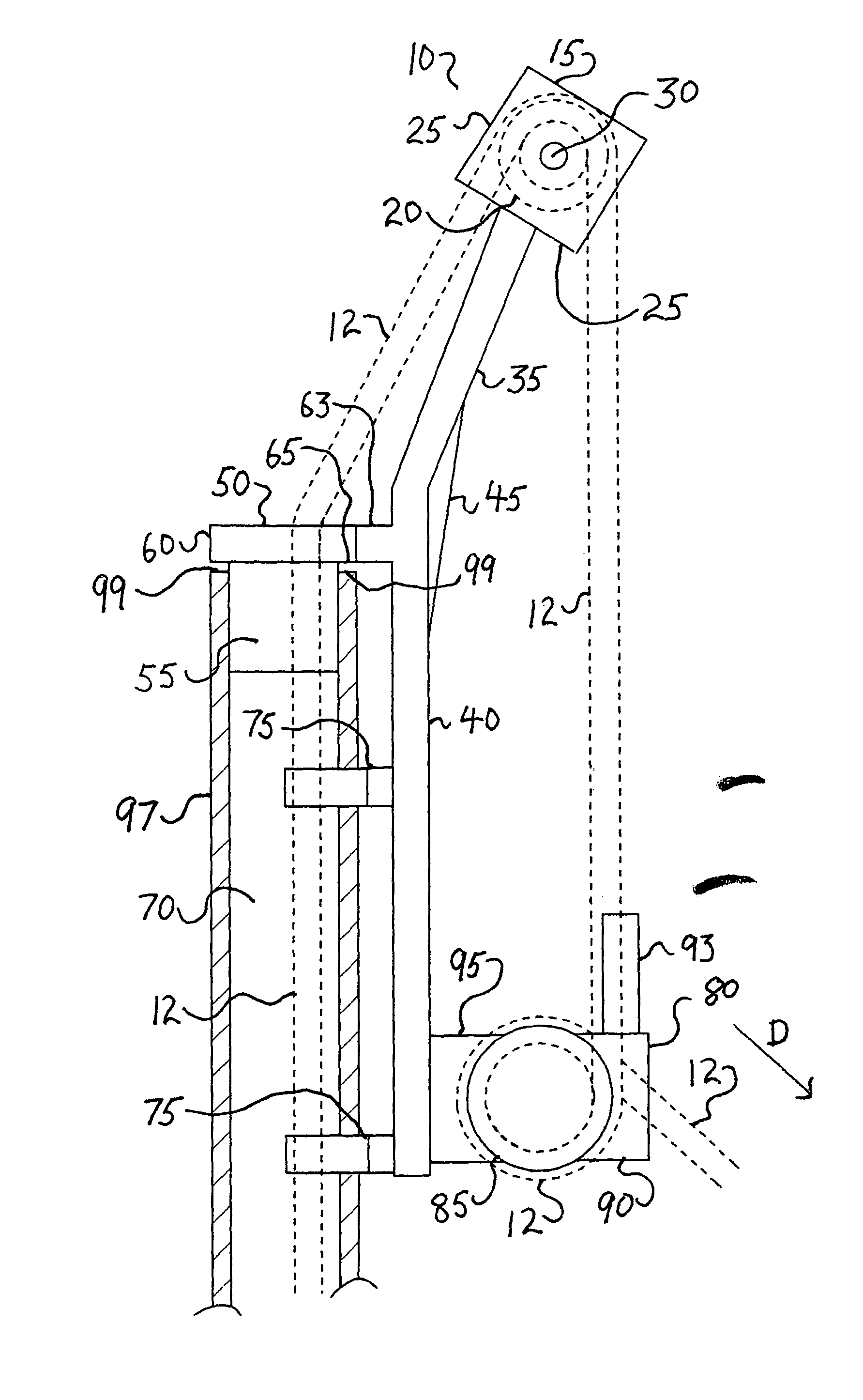
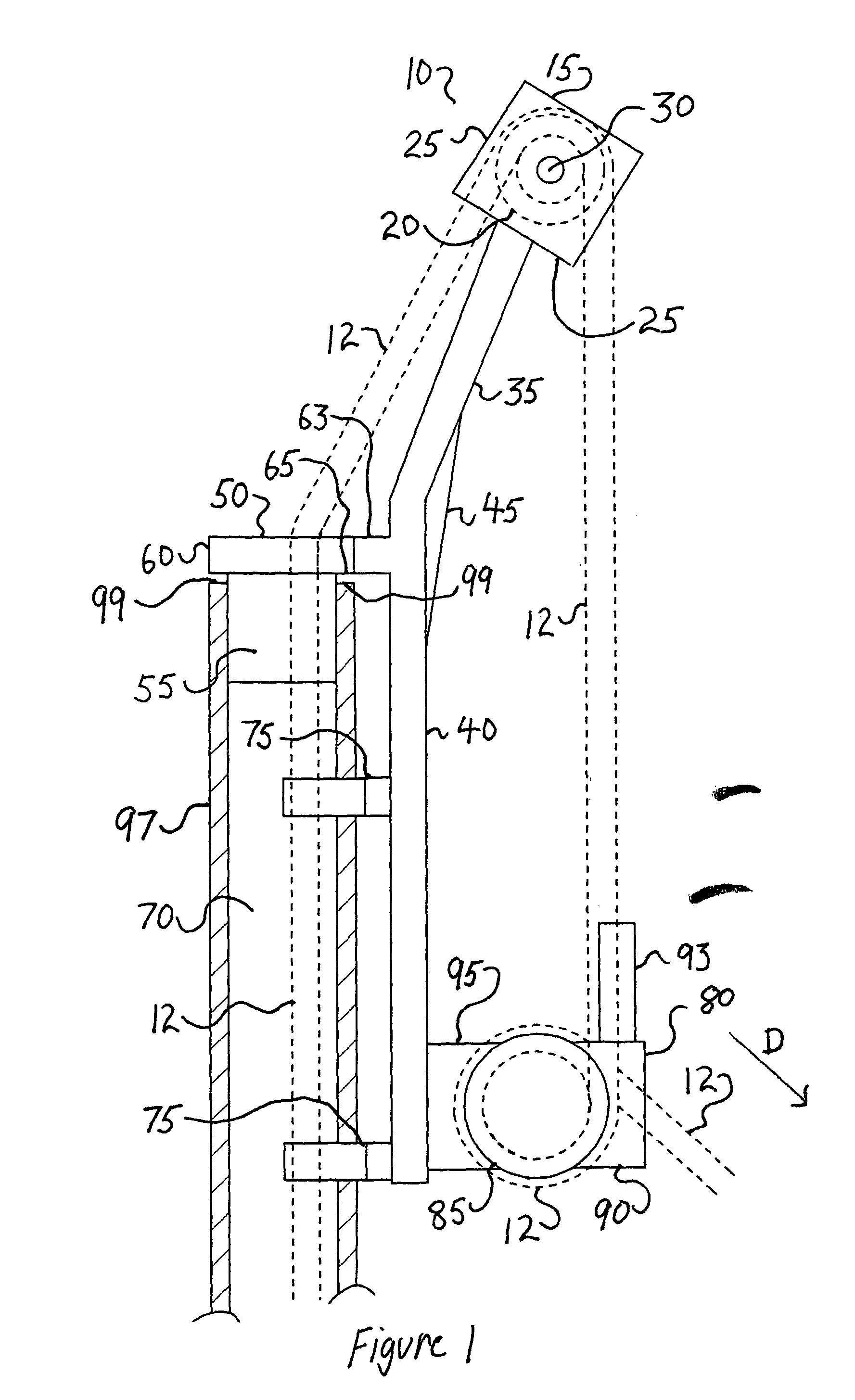
[0090]Looking now at FIG. 1, we see a conduit (97), shown in cut-away, having a lip (99) and a wire passage (70) extending substantially vertically. We understand that this conduit (97), and more particularly the lip, (99) is a terminus of a possibly underground, substantially horizontal conduit section, comprised by the conduit (97), running to an origin (not shown) that may be hundreds of feet away from the terminus. Furthermore, we recognize that in order to pull a heavy cable through the conduit (97) from the origin to the termin...


PUM


Abstract

A device for pulling wire through a conduit with sheave head, sheave head support boom, wire puller frame, conduit interface, and wire pull assembly. The wire pull assembly further comprises a capstan, a gear box having an input axle and an output axle, and a means to interface a power source to impart rotating force to the capstan.

Description

CROSS REFERENCE TO RELATED APPLICATIONS[0001]Not ApplicableSTATEMENT REGARDING FEDERALLY SPONSORED RESEARCH OR DEVELOPMENT[0002]Not ApplicableDESCRIPTION OF ATTACHED APPENDIX[0003]Not ApplicableBACKGROUND OF THE INVENTION[0004]This invention relates generally to the field of wire movement and more specifically to a machine for pulling wire through a conduit.[0005]The simple act of pulling wire through conduit is an art of continuously growing importance as on-the job muscle strain and long term back injury become increasingly common in installation of new communications and power systems. Generally speaking, a new building or structure must be internally wired and that internal wiring then interfaced with an external power or communications grid. For electrical power systems, the interface point is usually an electric meter box, affixed to the exterior of the building. The incoming wires of the power grid are frequently supported by utility poles placed along a road or thoroughfare ...

Claims


Application Information

Patent Timeline
Patent Type & Authority Patents(United States)
IPC IPC(8): H02G1/08E21C29/16
CPCH02G1/08
Inventor JERNIGAN, SCOTT ALAN
Owner JERNIGAN SCOTT ALAN
Why Eureka
Try Eureka