
Method for transmitting data in a MIMO telecommunication system offering a high diversity as perceived from a receiver end

a telecommunication system and data technology, applied in the field of telecommunication system data transmission, can solve the problem of limiting the performance of space-time decoders, and achieve the effects of improving decoding performance, increasing the diversity of input data, and improving quality

Inactive Publication Date: 2010-05-11
MITSUBISHI ELECTRIC R&D CENTRE EUROPE BV +1
View PDF5 Cites 4 Cited by
  • Summary
  • Abstract
  • Description
  • Claims
  • Application Information

AI Technical Summary

Benefits of technology

[0007]The inventors have observed that increasing the diversity of input data perceived by a front-end detector included in a space-time decoder enables said decoder to converge more quickly towards reliable estimates of the coded bits on the basis of which said data has been generated. This may be construed as obtaining better decoding performance by feeding the decoder with data having a higher quality, i.e. a richer content.
[0015]This specific embodiment of the invention is quite easy to implement, and thus enables to obtain an increased diversity at a relatively low cost in terms of computing resources and processing power required at the transmitting end, which is an important issue in the field of mobile communications where the transmitter may be constituted by a mobile terminal such as a mobile phone, which has to be as small as possible and will be power-fed by a battery having a limited energy storage capacity.
[0018]A spreading matrix according to this first variant enables an essentially homogeneous distribution over time of energy carried by the symbols transmitted through ergodic communication channels and ensures optimal detectability of changes in the communication conditions from one time chip to another. This in turn enables to provide a high diversity with respect to time and space of the data as perceived by receiving antennas at the receiver end of such ergodic communication channels.
[0020]Thanks to the orthogonality between chunks, a spreading matrix according to this second variant enables to add ergodicity to essentially invariant channels, during the time interval needed for transmitting the linear combinations of all components of the predetermined number of successive symbols, and additionally provides an essentially homogeneous distribution over this time interval of the energy carried by the symbols transmitted through said communication channels, which ensures optimal detectability of changes in the communication conditions from one time chip to another. This in turn enables to provide a high diversity with respect to time and space of the data as perceived by receiving antennas at the receiver end of such essentially invariant communication channels.
[0025]This in turn enables to provide a high diversity with respect to time and space of the data as perceived by receiving antennas at the receiver end of such block-fading communication channels.
[0027]The use of a rotation matrix for computing the plurality of linear combinations of components of successive symbols at the transmitter end enables to optimize global performance of the iterative space-time decoder intended to process said symbols at the receiver end, by enhancing the performance of the first iterative step performed by said decoder.

Problems solved by technology

The spatial diversity perceived by the receiving antennas, which is obtained by using multiple communication channels, though producing the above-mentioned advantages, is limited by the number of receiving antennas, which in turn limits the performance of the space-time decoder.

Method used


Image

  • Method for transmitting data in a MIMO telecommunication system offering a high diversity as perceived from a receiver end
  • Method for transmitting data in a MIMO telecommunication system offering a high diversity as perceived from a receiver end
  • Method for transmitting data in a MIMO telecommunication system offering a high diversity as perceived from a receiver end

Examples


Embodiment Construction

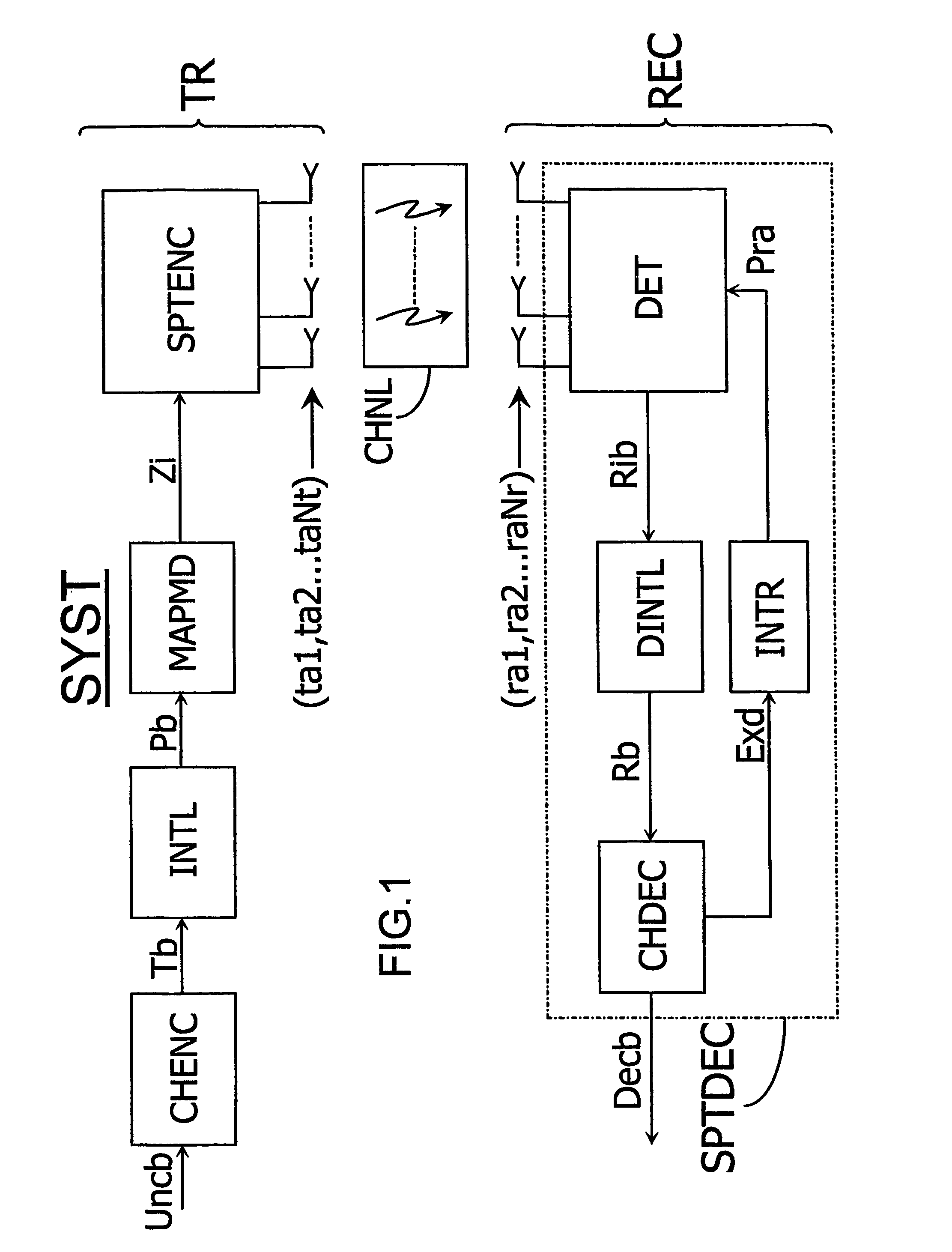
[0042]FIG. 1 diagrammatically shows a telecommunication system including at least one transmitter TR and one receiver REC, intended to exchange signals through multiple communication channels CHNL established between Nt transmitting and Nr receiving antennas (ta1,ta2 . . . taNt) and (ra1,ra2 . . . raNr), respectively.

[0043]The transmitter TR shown in the example depicted here includes a channel encoder CHENC intended to apply an encoding, e.g. by means of a convolutional code or of a turbo code, to uncoded data bits Uncb, and to provide a binary stream Tb to be transmitted. The transmitter TR includes an interleaver INTL intended to generate permutated bits Pb, such an interleaving being useful for a later processing on the receiver side, since it will allow to obtain uncorrelated data. The permutated bits Pb are then divided into sequences of Nt words of at least one bit each, which word sequences are then mapped, i.e. transformed into a series of coded symbols Zi by a mapping and ...


PUM


Abstract

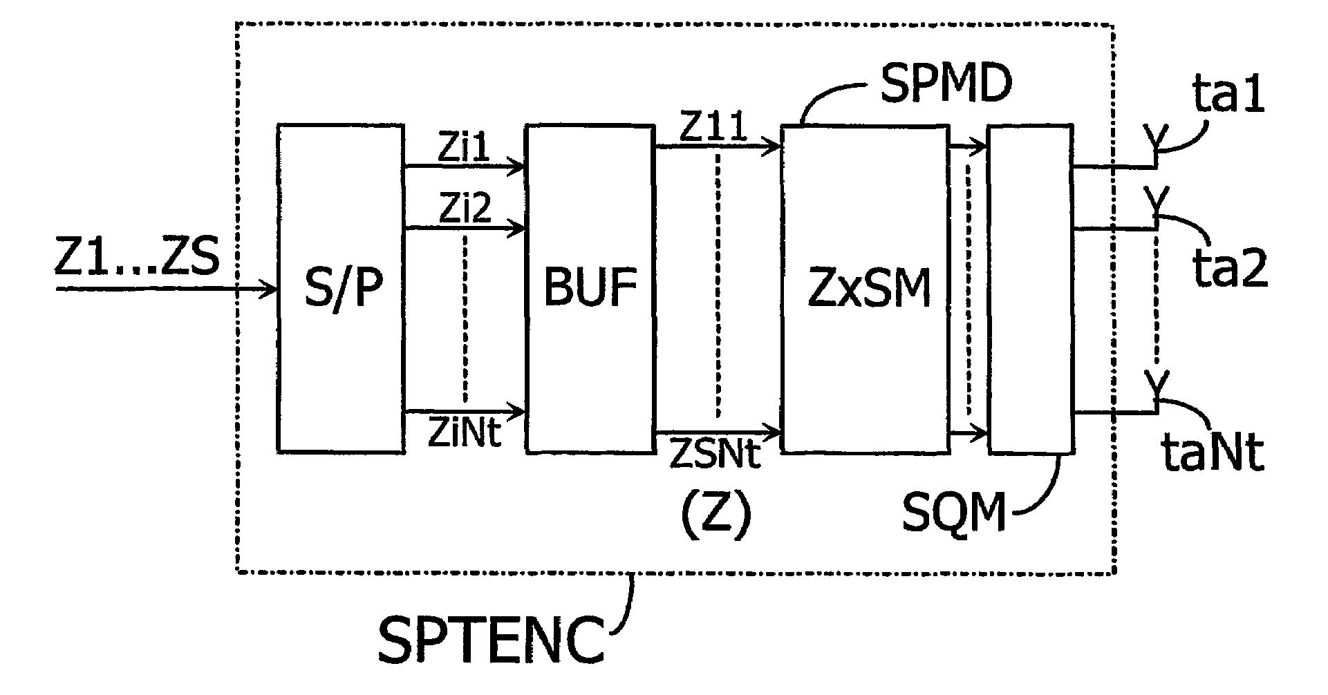
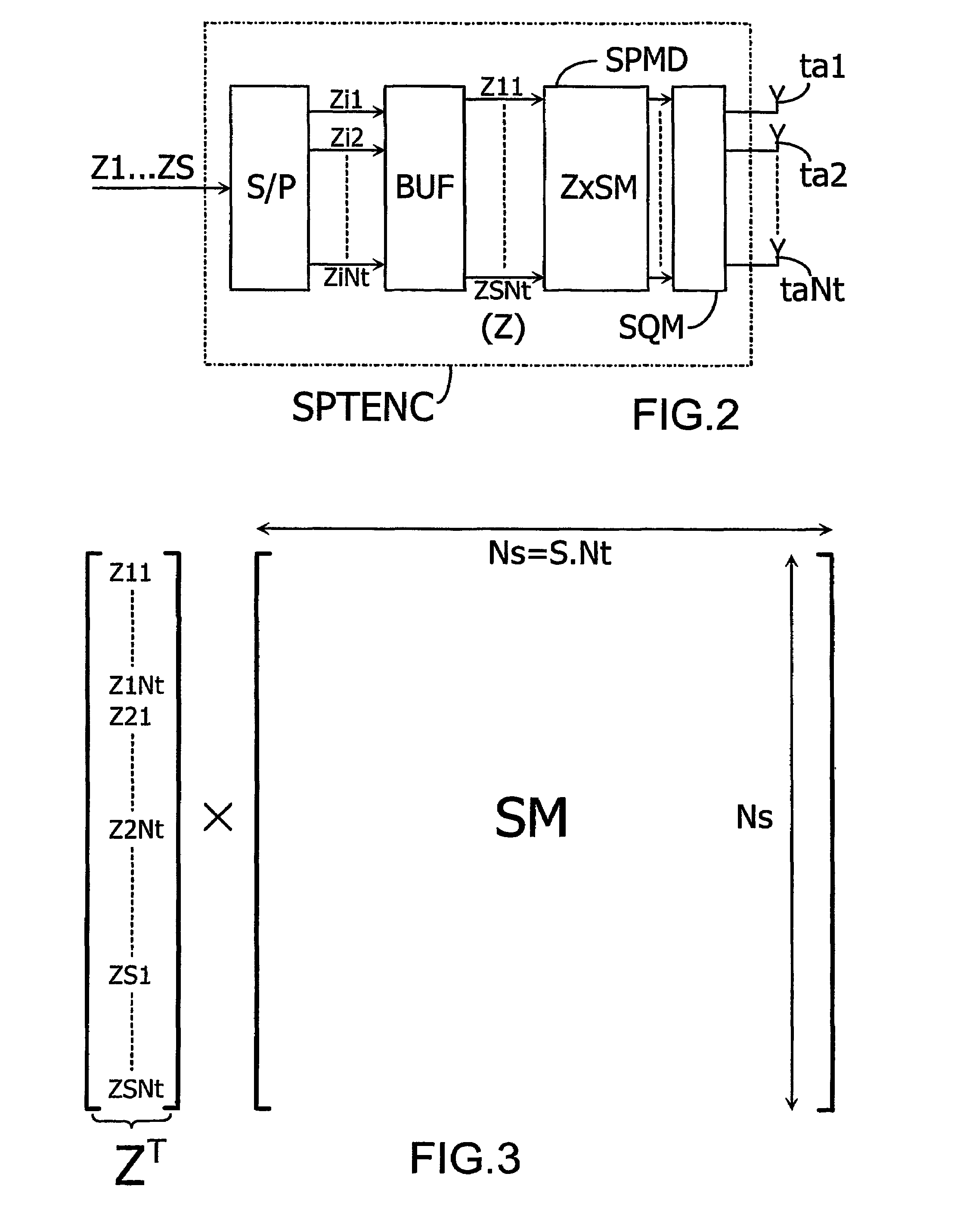
The present invention relates to a method for transmitting data between a transmitter provided with at least two transmitting antennas (ta1, ta2 . . . taNt) and a receiver. The method according to the invention further includes a symbol spreading step in the course of which components Zij (for i=I to S and j=I to Nt) of a predetermined number of successive symbols ZI . . . ZS are to be spread over time before being transmitted over said transmitting antennas (ta1, ta2 . . . taNt). The data transmitted at any given moment will thus not be representative of a single symbol Zi (for i=1 to S), as is the case in known MIMO systems, but will represent a mixture between Nt components of S successive symbols, which introduces data diversity with respect to time as perceived at the receiver end.

Description

BACKGROUND OF THE INVENTION[0001]1. Field of the Invention[0002]The present invention relates to a method for transmitting data in a telecommunication system including at least one transmitter provided with at least two transmitting antennas and at least one receiver provided with at least one receiving antenna, which method includes a symbol encoding step for producing symbols to be transmitted over communication channels established between the transmitting and receiving antennas.[0003]2. Discussion of the Background[0004]Telecommunication systems in which a plurality of antennas are used at a receiver end and / or at a transmitter end of a wireless link are called Multiple Input Multiple Output systems (further referred to as MIMO systems). MIMO systems have been shown to offer large transmission capacities compared to those offered by single antenna systems. In particular, MIMO capacity increases linearly with the number of transmitting or receiving antennas, whichever the smalles...

Claims


Application Information

Patent Timeline
Patent Type & Authority Patents(United States)
IPC IPC(8): H03C7/02H04B7/04H04J99/00H04L1/06
CPCH04B7/04H04L1/0643H04L1/0625H04B7/0669
Inventor GRESSET, NICOLASBRUNEL, LOICBOUTROS, JOSEPH
Owner MITSUBISHI ELECTRIC R&D CENTRE EUROPE BV
Learn More