
Vibration reducing device

a technology of vibration reduction and fuel injector, which is applied in the field of devices for reducing vibration, can solve the problems of generating an error known as aliasing, folding noise, and high cost of digital controller types, and achieve the effect of preventing aliasing and reducing vibration of the fuel injector

Inactive Publication Date: 2010-05-11
NISSAN MOTOR CO LTD
View PDF9 Cites 11 Cited by
  • Summary
  • Abstract
  • Description
  • Claims
  • Application Information

AI Technical Summary

Benefits of technology

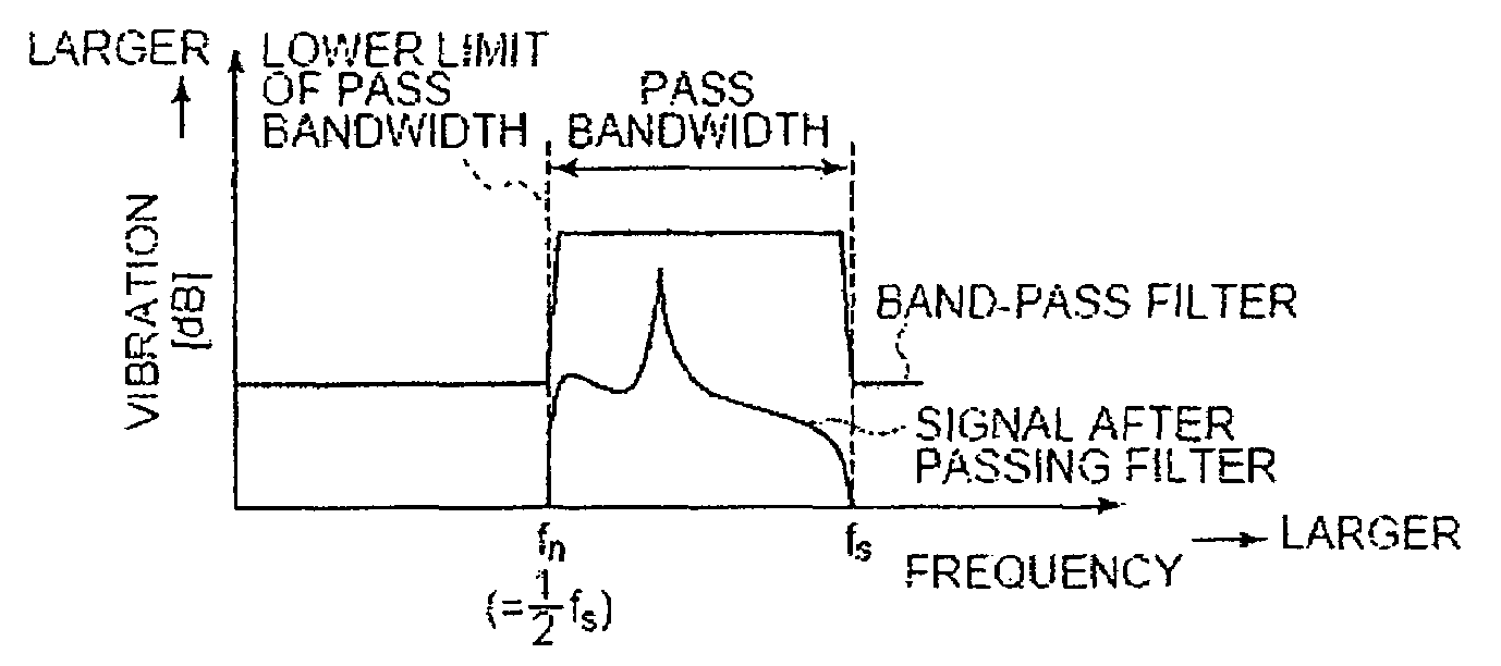
[0007]The present inventors have proposed the following arrangement: an actuator prepared by laminating thin sheet-shaped piezoelectric elements that stretch in the axial direction corresponding to an applied voltage is arranged between the cylinder head seat surface and the fuel injector, and by feeding back the acceleration in the axial direction of the fuel injector, the vibration of the fuel injector is reduced. However, for a digital controller, when the original signal contains high-frequency components that exceed one-half of the sampling frequency (i.e. the Nyquist frequency), the high-frequency components are folded at the Nyquist frequency and are superimposed on the original signal, generating an error known as aliasing (i.e. folding noise). In order to prevent aliasing, usually the high-frequency components that exceed the Nyquist frequency are eliminated with a low-pass filter (i.e. high-cut filter).
[0009]An object of the present invention is to solve the aforementioned problems of the related art by providing a vibration reducing device that can execute control without generating error for the high frequency region above the Nyquist frequency of the digital controller.

Problems solved by technology

However, for a digital controller, when the original signal contains high-frequency components that exceed one-half of the sampling frequency (i.e. the Nyquist frequency), the high-frequency components are folded at the Nyquist frequency and are superimposed on the original signal, generating an error known as aliasing (i.e. folding noise).
However, these types of digital controllers are costly.

Method used


Image

  • Vibration reducing device
  • Vibration reducing device
  • Vibration reducing device

Examples


embodiment 1

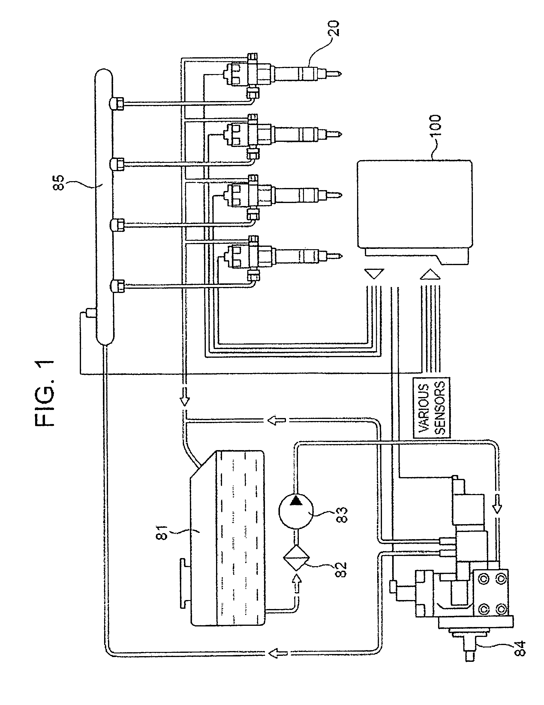
[0022]FIG. 1 is a diagram illustrating a fuel supply system with fuel injectors to which the vibration reducing device of the present invention has been applied. This fuel supply system shown is used in common rail type diesel engines for automobiles.

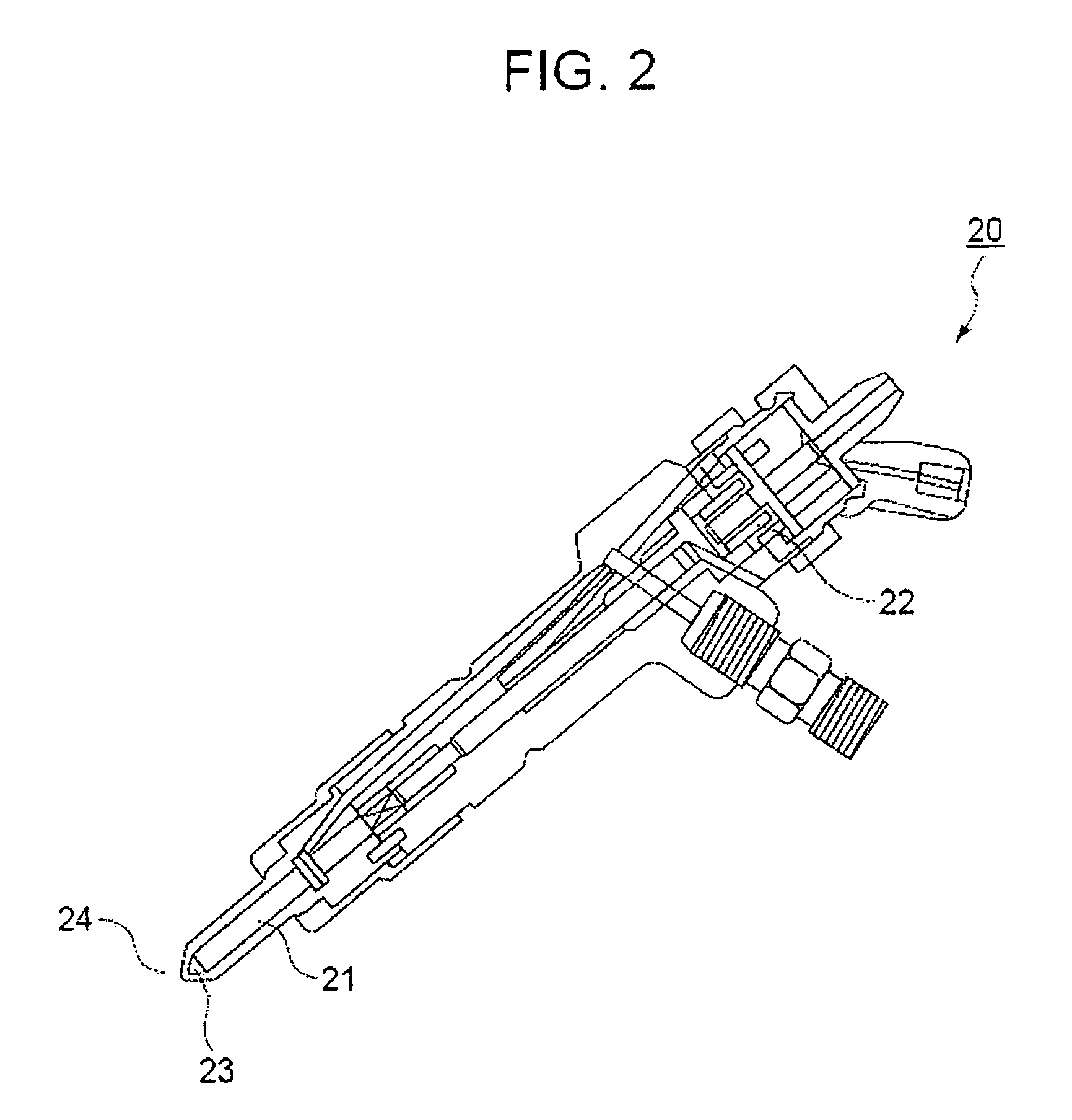
[0023]The fuel in fuel tank 81 is pumped out with low pressure pump 83 via filter 82, compressed to a high pressure state by high-pressure supply pump 84, and fed to common rail 85. High-pressure supply pump 84 contains a pressure regulator. As a result, the excess fuel is returned to fuel tank 81, and the pressure in common rail 85 is controlled to the prescribed level. The high-pressure fuel is fed from common rail 85 to each fuel injector 20, and as fuel injector 20 is driven to open the valve, the fuel is directly sprayed into each cylinder.

[0024]The operation of fuel injector 20 is controlled by controller 100. The controller 100 computes the fuel injection time and fuel injection quantity on the basis of the load on the engine (vi...

embodiment 2

[0055]FIG. 8 is a diagram illustrating another embodiment of the fuel injector vibration reducing device of the present invention. The same part numbers that were used in the aforementioned embodiment are used again here; their detailed explanation will not be repeated.

[0056]Input-side bandpass filter 104c, A / D conversion part 102c, digital controller 101c, D / A conversion part 103c, and bandpass filter 105c substantially corresponds to those having same part number in the aforementioned embodiment. On the other hand, input-side bandpass filter 104b, A / D conversion part 102b, digital controller 101b, D / A conversion part 103b, and output-side bandpass filter 105b are added as additional elements of the vibration reducing device. The digital controller 101b is connected with the acceleration sensor 25 (vibration state detection device) and the piezoelectric element 10 (the actuator) as a second digital controller. The input-side bandpass filter 104b arranged between the acceleration se...


PUM


Abstract

A vibration reducing device that reduces the vibration of a control object includes a digital controller. A vibration state detection device detects the vibration of the control object and generates an analog signal of the vibration of the control object. An input-side bandpass filter has a passband that is narrower than a frequency range from a Nyquist frequency to a sampling frequency of the digital controller, and that contains no frequencies that are an integer multiple of the Nyquist frequency of the digital controller. The input-side bandpass filter allows a part of the analog signal that falls within the passband from the analog signal generated by the vibration state detection device to pass. An A / D conversion device converts the analog signal that has passed through the input-side bandpass filter into a digital signal. A D / A conversion device converts a digital feedback control signal, determined by the digital controller on the basis of the digital signal converted by the A / D conversion device, into an analog feedback control signal. An actuator applies vibration to the control object on the basis of the analog feedback control signal converted by the D / A conversion device.

Description

CROSS-REFERENCE TO RELATED APPLICATIONS[0001]This application claims priority under 35 U.S.C. §119 to Japanese Patent Application Nos. 2006-294546, filed on Oct. 30, 2006, and 2007-193112 filed Jul. 25, 2007, the disclosures of which are incorporated by reference herein in the entirety.BACKGROUND OF THE INVENTION[0002]1. Field of the Invention[0003]The present invention relates to a device for reducing the vibration of a control object, which can be applied to reduce the high-frequency vibration of the control object. A fuel injector of an internal combustion engine is one such control object that has a high-frequency vibration to be reduced.[0004]2. Description of Related Art[0005]In a direct-injection diesel engine, fuel that has been compressed to a high pressure is directly sprayed into the cylinders by fuel injectors. The fuel injectors may be supported, for example, by known structures. That is, the fuel injector may be installed in a fuel injector mounting hole formed in the ...

Claims


Application Information

Patent Timeline
Patent Type & Authority Patents(United States)
IPC IPC(8): G06F19/00F16F7/10G21C17/00F02M61/16F16F15/02G05B13/02G05D19/02
CPCF02M61/14F16F15/02F02M2200/09F02M2200/302F02M2200/21
Inventor SATO, YUSUKENUNOME, YOSHIMIFUJIKANE, KAZUHIRO
Owner NISSAN MOTOR CO LTD
Learn More