
Surface texture measuring instrument

a technology of surface texture and measuring instrument, which is applied in the direction of speed/acceleration/shock measurement device testing/calibration, electric/magnetic measuring arrangement, compasses, etc., can solve the problem of not being able to acquire acceleration, the resolution of the correction amount is also deteriorated to one hundredth, and the insufficient to meet the demand for high-speed and highly accurate measuremen

Active Publication Date: 2010-05-11
MITUTOYO CORP
View PDF9 Cites 9 Cited by
  • Summary
  • Abstract
  • Description
  • Claims
  • Application Information

AI Technical Summary

Benefits of technology

[0054]Since the correction amount is determined by the correction-amount calculating unit based on the estimated operation state quantity, the correction amount for correcting the deformation generated on the currently-driven drive mechanism can be accurately calculated.
[0105]Further, since the continuation or termination of the correction calculation can be determined based on the judgment, erroneous measurement result output on account of erroneously correcting the measurement data can be prevented.

Problems solved by technology

Consequently, the resolution of the correction amount is also deteriorated to one hundredth.
As discussed above, it is not practical to acquire the acceleration by differentiating the position twice and is insufficient to meet the demand for high-speed and highly accurate measurement.
Accordingly, accuracy of correction is limited in principle when the acceleration is obtained on the measurement slider.
However, it is difficult to provide an acceleration sensor capable of detecting 50 μG acceleration for each of movement axes (totaling three).
Furthermore, it is impossible to provide such acceleration sensors around the probe unit.
Accordingly, it is not possible for a traditional arrangement to accurately measure a deformation caused during scanning measurement and such deformation cannot be compensated.
Thus, the profile of the object cannot be accurately obtained during high-speed measurement, so that the measurement speed is limited to a level that causes no deformation in order to conduct an accurate measurement.

Method used


Image

  • Surface texture measuring instrument
  • Surface texture measuring instrument
  • Surface texture measuring instrument

Examples


first embodiment

[0130]A surface texture measuring instrument according to a first embodiment of the invention will be described below.

[0131]FIG. 20 shows a surface scanning measuring instrument according to the first embodiment in the form of a measuring system 100 that utilizes a scanning probe 130.

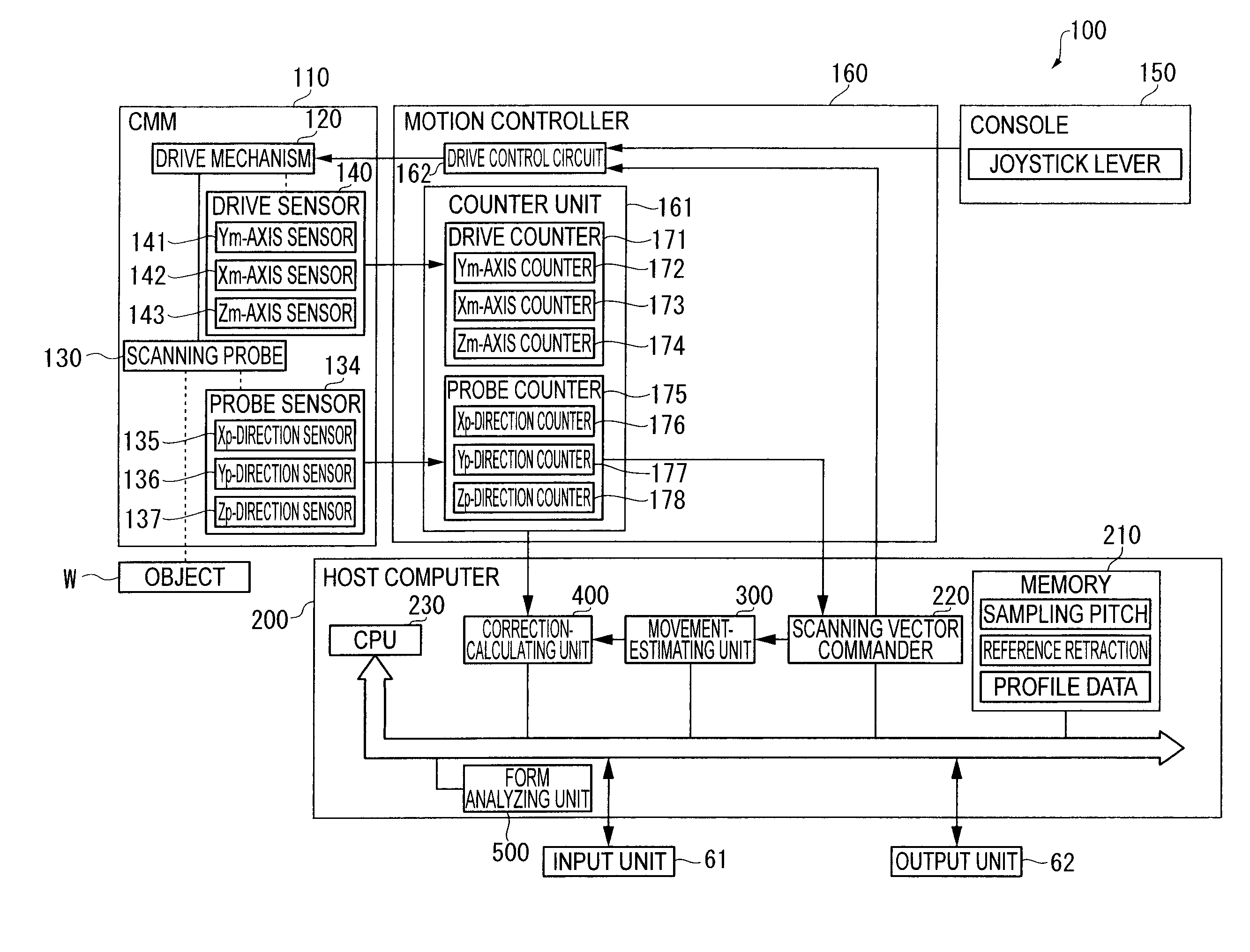
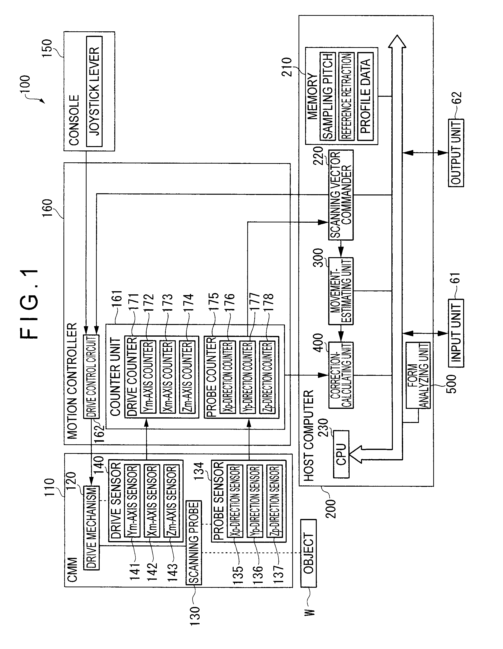
[0132]FIG. 1 shows a functional block diagram showing the measuring system 100.

[0133]The measuring system 100 is constructed in the same manner as what has been described in the Background section, which includes a CMM 110, a console 150 for manually controlling the operation of the CMM 110, a motion controller 160 for executing drive control of the CMM 110, a host computer 200 that sends a predetermined command to the motion controller 160 and conducts calculation processing such as profile analysis of an object W, an input unit 61 through which a measurement condition and the like are input, and an output unit 62 that outputs a measurement result.

[0134]The CMM 110 includes (see FIG. 20): a table 111; ...

second embodiment

[0212]Next, a surface scanning measuring instrument according to a second embodiment of the invention will be described below.

[0213]The basic arrangement of the second embodiment is the same as the first embodiment except that the deformation caused on account of centrifugal force during the rotary movement is corrected in the second embodiment.

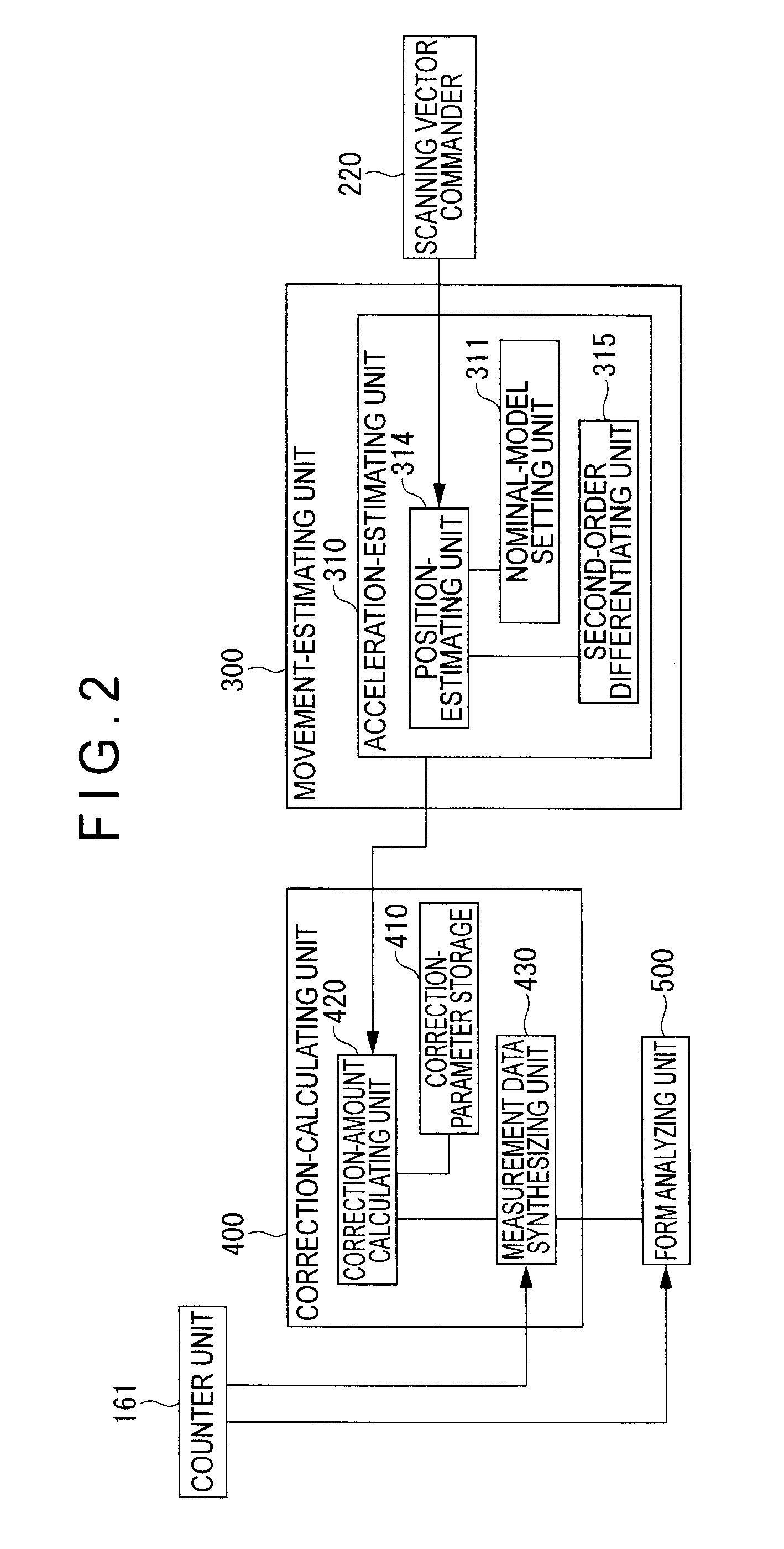
[0214]FIG. 4 shows a movement-estimating unit 600 and a correction-calculating unit 700 according to the second embodiment.

[0215]The movement-estimating unit 600 includes the acceleration estimating unit 310 and a frequency-estimating unit 610.

[0216]The frequency-estimating unit 610 estimates the rotary frequency of the rotary movement of the scanning probe 130.

[0217]The acceleration A is calculated by the second-order differentiating unit 315. The acceleration A (ax, ay, az) calculated by the second-order differentiating unit 315 is input into the frequency-estimating unit 610.

[0218]When a rotation radius of the rotary scanning measurement a...

third embodiment

[0350]Next, a third embodiment of the invention will be described below.

[0351]The basic arrangement of the third embodiment is the same as that of the second embodiment. The distinctive feature of the third embodiment is the provision of an estimation-judging unit 800 for judging the accuracy of the acceleration estimation by comparing the acceleration estimated value calculated by the movement-estimating unit 600 with actual acceleration is provided.

[0352]FIG. 19 is a block diagram showing an arrangement of the movement-estimating unit 600, the correction-calculating unit 700 and the estimation-judging unit 800 according to the third embodiment.

[0353]The estimation-judging unit 800 includes: an actual-acceleration calculating unit 810 for calculating the actual acceleration based on measurement value of the coordinates detected by the counter unit 161; a difference-calculating unit 820 for calculating the difference between the estimated acceleration calculated by the movement-esti...


PUM


Abstract

A surface texture measuring instrument includes: a movement-estimating unit for estimating a movement condition of a drive mechanism based on a scanning vector command issued by a scanning vector commander to calculate an estimated operation state quantity; and a correction-calculating unit for correcting a detection value of a drive sensor in accordance with the estimated operation state quantity calculated by the movement-estimating unit. The movement-estimating unit includes: a nominal-model setting unit in which a nominal model representing signal transfer function of the scanning vector command from the issuance of the scanning vector command to a reflection on a movement position of the scanning probe is stored. The correction-calculating unit includes a correction-amount calculating unit that calculates a correction amount for correcting a measurement error generated on account of deformation during the drive of the drive mechanism based on the estimated operation state quantity; and a measurement data synthesizing unit that synthesizes the detection value of the drive sensor and a detection sensor and the correction amount calculated by the correction-amount calculating unit to acquire a measurement data.

Description

BACKGROUND OF THE INVENTION[0001]1. Field of the Invention[0002]The present invention relates to a surface texture measuring instrument.[0003]Specifically, it relates to, for instance, a surface scanning measuring instrument that scans an object surface to measure a profile, surface roughness, waviness and the like of an object to be measured.[0004]2. Description of Related Art[0005]A surface scanning measuring instrument that scans an object surface to measure a three-dimensional profile of an object has been traditionally known.[0006]FIG. 20 shows an arrangement of a measurement system 100 as an example of a surface scanning measuring instrument that utilizes a scanning probe 130.[0007]The measurement system 100 includes: a coordinate measuring machine (CMM) 110 that moves a scanning probe 130; a console 150 for manually operating the CMM 110; a motion controller 160 for controlling the operation of the CMM 110; and a host computer 200 that operates the CMM 110 through the motion ...

Claims


Application Information

Patent Timeline
Patent Type & Authority Patents(United States)
IPC IPC(8): G01B5/008
CPCG01B5/28G01B5/008
Inventor KIYOTANI, SHINGO
Owner MITUTOYO CORP
Learn More