
Method and system for integrated orthodontic treatment planning using unified workstation

a workstation and integrated technology, applied in the field of computerized orthodontic treatment planning, can solve the problems of large volume of images and data involved, limited functionalities and scope, and large amount of manual work involved in these steps

Inactive Publication Date: 2010-05-18
ORAMETRIX
View PDF30 Cites 115 Cited by
  • Summary
  • Abstract
  • Description
  • Claims
  • Application Information

AI Technical Summary

Benefits of technology

[0022]The method and workstation further involves using the graphical user interface to a) evaluate space between the virtual teeth and arch length requirements, b) evaluate the effect of various constraints on the arch length, and design a desired arch form for the patient, and c) move virtual teeth in a three-dimensional model of the patient from an initial orientation relative to the desired arch form, occlusal plane, midline, tooth position, reference tooth so as to arrive at a proposed tooth arrangement for treatment of the patient. Furthermore, the interdependency of the constraints can be evaluated. Preferably, the user interface provides tools that enable the practitioner to perform the task of space management between teeth in each arch to assure that there would be adequate space to accommodate the contemplated teeth alignment. Space management is done with respect to mandible and maxilla, both at the intra arch and inter arch level.
[0025]In another embodiment of the invention, assignment of values to variables, such as markings, tooth alignment, and space allocation, is integrated in a manner such that the most current selection or value for each such variable is retained by the workstation and made available at any other step in the treatment planning process besides the one where the specific value was originally assigned. For example, the midline marking done first on the 2D photos of the patient will be shown in the same position on appropriate 3D model of the patient's teeth used in teeth alignment and space management. The converse is also true, i.e., markings on a 3D virtual patient model will be available in 2D images of the same patient. An aspect of this invention is that a variable (such as the location of the midline in a 2D photograph) may be assigned a certain value at one step, and be modified at another step. Such integration is realized through proper scaling and synchronization of patient's characteristics and features prevalent through 2D photographs and 2D and 3D images and models. A major benefit of this invention is that throughout the treatment planning process patient's biological interdependence between soft tissue, skeletal, and dental disposition is maintained and resulting constraints applied in a consistent manner such that unfeasible treatment options are filtered out. In turn, the benefit results in producing efficient and cost effective treatment plans. Additionally it is possible to stage treatment and compare progress against the staged treatment. The treatment plan can be actuated or initiated at any point in treatment to respond to any change that may occur.
[0026]In yet another aspect of the invention, the unified workstation facilitates simulation of realizing the target treatment objective through a number of staged incremental or step-wise treatment plans. The treatment increments can be varied and its impact seen on associated teeth disposition and space management. A practitioner can use this process in an interactive and dynamic manner to evaluate several treatment scenarios. A major benefit of this invention is that it enables the practitioner and the patient to tailor the treatment plan that best suits the patient needs.
[0027]In yet another embodiment of the invention, the unified work station facilitates rapid selection of treatment plan driven by templates. The practitioner provides specific values or ranges of values for the treatment parameters, such as for midline, maxilla and mandible levels and cant for aesthetic occlusal plane, various positions for upper and lower occlusal planes, reference tooth, arch form and alignment parameters for teeth, and space requirements, etc. for patient. The unified workstation, using computer instructions based tools, searches a clinical benchmarking knowledge base consisting of reference treatment plans for a large number of individual patients for a reference treatment plan. The search essentially cross-references using parameter values (e.g., archform shape, diagnosis, appliance type, etc.) and successful treatments and finds the most suitable reference treatment, if one is available in the knowledge base. In one possible embodiment, the workstation enables the practitioner to create and update such knowledge base through a self-learning process aided by computer instruction tools resident in the unified workstation.
[0029]In yet another embodiment of the invention, the unified workstation provides computer software instruction in the form of user interface tools that aid in treatment planning in a number of ways. For example, original teeth models can be superimposed on the aligned teeth model, where original teeth positions are shown in one color and the aligned teeth in another color, to visualize the effect of teeth disposition. Constraints (e.g., midline, occlusal plane, etc.) can be defined both in 2D and 3D images. They are interchangeable and changes made in 3D are applied automatically in 2D and vice versa. Occlusal planes can be superimposed on 3D teeth model to display malocclusion of the original teeth, and the combination further superimposed on the model of the properly aligned teeth to see the improvement. The midline can be superimposed on 3D teeth models. Three-dimensional gingival tissue, obtained from an intra-oral scan, can be superimposed on 3D teeth model at any stage in the treatment planning process. In a representative embodiment, color coding is invoked to show different aspects of the display. A grid can be superimposed on 3D teeth model to aid in visualizing certain measurements. Animation light can be thrown on 3D teeth model, and teeth can be shaded based upon their location with respect to the animated light source so as to aid in viewing otherwise difficult to see detailed teeth features. This can also be done while 3D teeth model is rotated to give views from different angles.

Problems solved by technology

Thus, there is a large volume of images and data involved in the diagnosis and treatment planning process.
There are some computerized tools available to aid the practitioner in these data conversion and reduction steps, for example to convert cephalometric x-rays (i.e., 2 dimensional x-ray photographs showing a lateral view of the head and jaws, including teeth) into points of interest with respect to soft tissue, hard tissue, etc., but they are limited in their functionalities and scope.
Even then, there is a fairly substantial amount of manual work involved in these steps.
Generally, these steps are time consuming and prone to inherent inaccuracies.
Furthermore, the practitioner has to contend with the biological interdependencies within the patient, which introduces constraints eliminating certain treatment options that would otherwise be acceptable, between the soft tissue, the hard tissue, and the teeth.
There is lack of an integrated platform which a practitioner could utilize to filter-out non-practicable treatment options.
Often, due to the complexities of the detailed steps and the time consuming nature of them, some practitioners take a short-cut, relying predominantly on their intuition to select a treatment plan.
All of these factors frequently contribute towards trial and error, hit-and-miss, lengthy and inefficient treatment plans that require numerous mid-course adjustments.
While at the beginning of treatment things generally run well as all teeth start to move at least into the right direction, at the end of treatment a lot of time is lost by adaptations and corrections required due to the fact that the end result has not been properly planned at any point of time.
By and large, this approach lacks reliability, reproducibility and precision.
More over, there is no comprehensive way available to a practitioner to stage and simulate the treatment process in advance of the actual implementation to avoid the often hidden pitfalls.
And the patient has no choice and does not know that treatment time could be significantly reduced if proper planning was done.
However, these approaches are limited to diagnosis and treatment planning of craniofacial structures, including the straightening of teeth.

Method used


Image

  • Method and system for integrated orthodontic treatment planning using unified workstation
  • Method and system for integrated orthodontic treatment planning using unified workstation
  • Method and system for integrated orthodontic treatment planning using unified workstation

Examples


Embodiment Construction

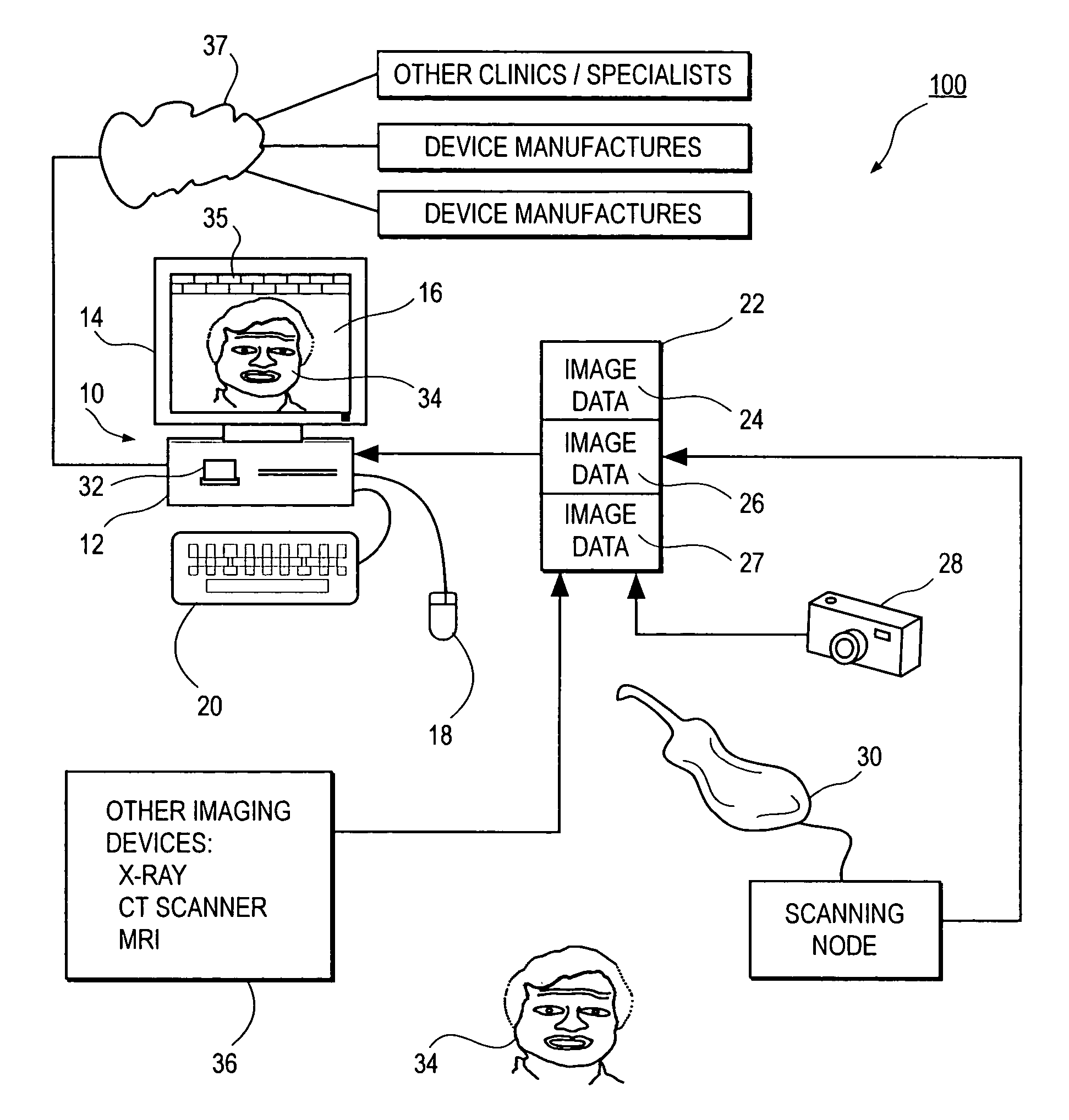
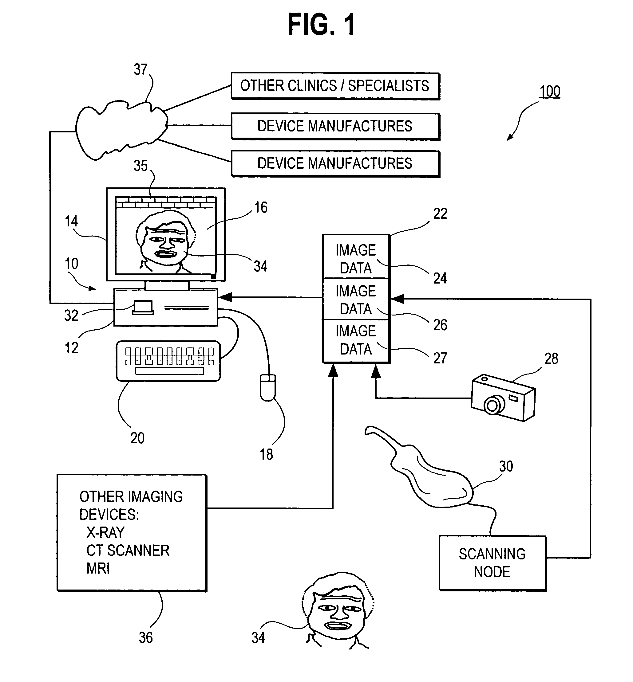
[0053]Before describing the treatment planning features of this invention in detail, an overview of a unified workstation will be set forth initially. The workstation, in a preferred embodiment, provides software features that create two dimensional and / or three-dimensional virtual patient model on a computer, which can be used for purposes of treatment planning in accordance with a presently preferred embodiment.

[0054]Many of the details and computer user interface tools which a practitioner may use in adjusting tooth position, designing appliance shape and location, managing space between teeth, and arriving at a finish tooth position using interaction with a computer storing and displaying a virtual model of teeth are set forth in the prior application Ser. No. 09 / 834,412 filed Apr. 13, 2001, and in published OraMetrix patent application WO 01 / 80761, the contents of which are incorporated by reference herein. Other suites of tools and functions are possible and within the scope o...


PUM


Abstract

A method and workstation for orthodontic treatment planning of a patient. The workstation is based on a computing platform having a graphical user interface, a processor and a computer storage medium containing digitized records pertaining to a patient including image data (3D image data and / or 2D image data). The workstation further includes a set of software instructions providing graphical user interface tools which the user marks a midline and an aesthetic occlusal plane in a two- or three-dimensional virtual model of the patient, marks an occlusal plane in the virtual model; selects a reference tooth in the virtual model; aligns virtual teeth in the virtual model in a proposed arrangement to treat the patient; manages space between the virtual teeth in the proposed arrangement; and repeats one or more of these steps in an iterative fashion to make any further adjustments in the proposed arrangement. When the adjustments are complete, the user selects or identifies a finalized proposed treatment plan for treating the patient.

Description

RELATED APPLICATIONS[0001]This is a continuation-in-part of application Ser. No. 09 / 834,412, filed Apr. 13, 2001 now U.S. Pat. No. 6,632,089 the entire contents of which are incorporated by reference herein.[0002]This application is related to patent applications filed on the same date as this application, entitled “UNIFIED WORKSTATION FOR VIRTUAL CRANIOFACIAL DIAGNOSIS, TREATMENT PLANNING AND THERAPEUTICS”, Rohit Sachdeva et al, inventors, Ser. No. 10 / 429,123 now U.S. Pat. No. 7,234,937, the entire contents of which are incorporated by reference herein, and entitled “INTERACTIVE UNIFIED WORKSTATION FOR BENCHMARKING AND CARE PLANNING”, Rohit Sachdeva et al, inventors, Ser. No. 10 / 429,074, the entire contents of which are incorporated by reference herein.BACKGROUND OF THE INVENTION[0003]A. Field of the Invention[0004]This invention relates to the field of computerized techniques for orthodontic treatment planning for human patients. More particularly, the invention is directed to an ...

Claims


Application Information

Patent Timeline
Patent Type & Authority Patents(United States)
IPC IPC(8): A61C3/00A61C7/00
CPCA61C7/00A61C9/0046G06F19/3437A61C7/002G06F19/3481G06F19/3406G16H20/40G16H40/63G16H50/50
Inventor SACHDEVA, ROHITSPORBERT, PEERMAETZEL, STEPHANIMGRUND, HANSSTRAUSS, CLAUDIAGETTO, PHILLIPTANEJA, SANJEEVJOHNSON, MATTHEWPENMAN, JOHNBADURA, JUSTYNADE SILVA, DANESH
Owner ORAMETRIX
Learn More