Method of obtaining a magnetic resonance image in which the streak artifacts are corrected using non-linear phase correction

Inactive Publication Date: 2010-05-18
SAMSUNG ELECTRONICS CO LTD
View PDF22 Cites 3 Cited by
  • Summary
  • Abstract
  • Description
  • Claims
  • Application Information

AI Technical Summary

Problems solved by technology

Due to the above limitation and characteristics, various artifacts such as Nyquist ghost and geometric distortion may be produced in finally reconstructed images.

Method used


Image

  • Method of obtaining a magnetic resonance image in which the streak artifacts are corrected using non-linear phase correction
  • Method of obtaining a magnetic resonance image in which the streak artifacts are corrected using non-linear phase correction
  • Method of obtaining a magnetic resonance image in which the streak artifacts are corrected using non-linear phase correction

Examples


Embodiment Construction

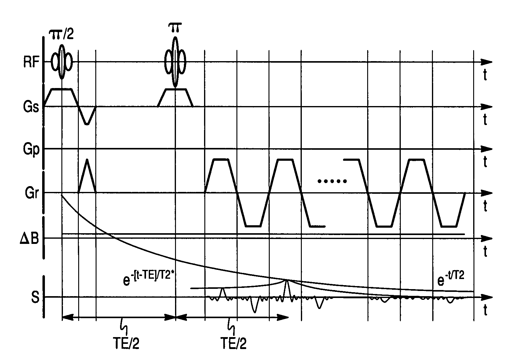
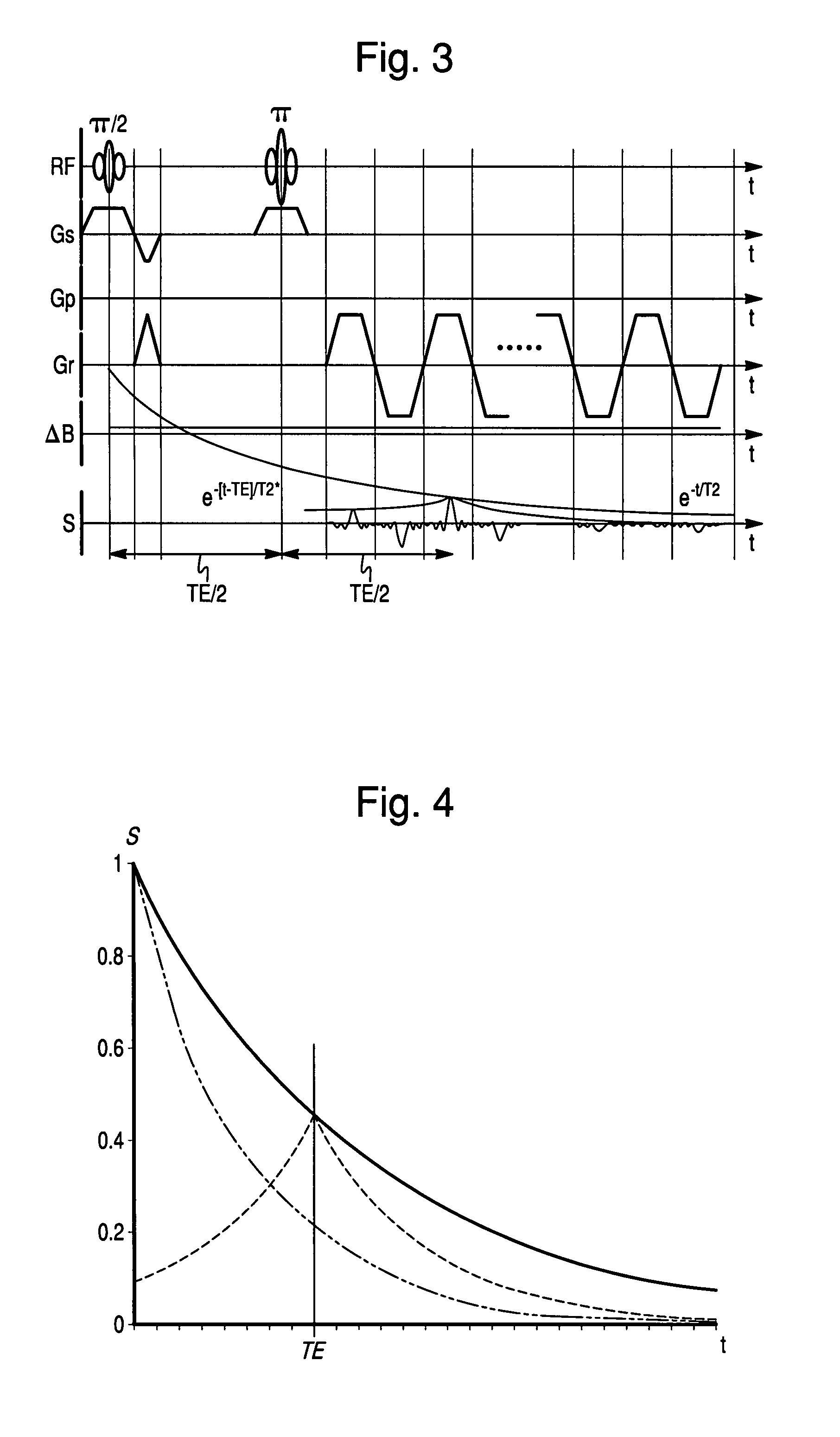
[0031]Hereinafter, an implementation of this document will be described in detail with reference to the attached drawings.

[0032]A streak artifact was first reported by Xiaoping Hu and Tuong Huu Le, entitled “Artifact Reduction in EPI with Phase-Encoded Reference Scan,”Magnetic Resonance in Medicine, 34, pp. 166-171, 1996. However, in this paper, it is briefly mentioned that an occurrence of streak artifact is associated with a signal-to-noise ratio (SNR), blood vessels, or a flow of cerebrospinal fluid.

[0033]1) Cause of Streak Artifact

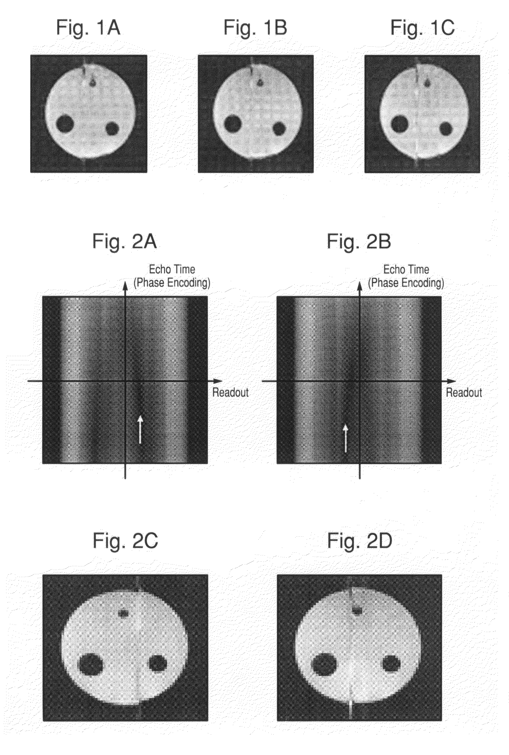
[0034]FIGS. 1(a)-1(c) illustrate images reconstructed using reference information acquired based on various variables in a conventional method.

[0035]A variable for acquiring gradient echo reference information was variously changed to find out whether the streak artifact mentioned in the above paper was caused by SNR. An experiment for this discovery was carried out using two average variables (e.g., number of excitation, which will be abbreviated as N...


PUM


Abstract

A non-linear phase correction method is provided. For the non-linear phase correction method, image information is acquired by gradient echo echo planar imaging (EPI). Reference information is acquired by spin echo EPI. The image information is corrected based on the reference information.

Description

[0001]This nonprovisional application claims priority under 35 U.S.C. §119(a) on Patent Application No. 10-2006-0131596 filed in Republic of Korea on Dec. 21, 2006, the entire contents of which are hereby incorporated by reference.BACKGROUND[0002]1. Field[0003]This document relates to a phase correction method, and more particularly, to a non-linear phase correction method.[0004]2. Related Art[0005]Magnetic resonance imaging (MRI) is used to acquire an accurate image of interior parts of a human body. MRI is based on a field of physics in nuclear magnetic resonance (NMR). Nuclei including an odd number of neutrons or an odd number of protons usually have a net magnetic moment, and are NMR active.[0006]Echo planar imaging (EPI), which is a high-speed MRI technique, is widely used in various fields including functional MRI (fMRI), diffusion tensor imaging (DTI), which is used to find out the position and direction of white matter fibrous tissues, cardiac function measuring imaging, di...

Claims


Application Information

Patent Timeline
Patent Type & Authority Patents(United States)
IPC IPC(8): G01V3/00
CPCG01R33/56554G01R33/56341G01R33/4806G01R33/563A61B5/055
Inventor PARK, HYUN WOOKCHUNG, JUN-YOUNG
Owner SAMSUNG ELECTRONICS CO LTD
Why Eureka
Try Eureka