
Compact keplerian optical system

a keplerian optical system and compact technology, applied in the field of magnification optics, can solve problems such as unsatisfactory cantilever effect, and achieve the effects of reducing overall length, minimizing eye strain, and increasing depth of field

Active Publication Date: 2010-05-18
GEN SCI
View PDF14 Cites 2 Cited by
  • Summary
  • Abstract
  • Description
  • Claims
  • Application Information

AI Technical Summary

Benefits of technology

[0006]This invention resides in a compact Keplerian optical system. The preferred embodiment includes a telescope having an image-rotator (Pechan-roof prism pair), and an eyepiece and objective lens. The objective forms an intermediate image plane within the prism, thereby decreasing the overall length. The outer objective lens (typically called a field lens) optionally forms part of a replaceable cap, and plurality of replaceable caps may be provided, each with a different focal length to adjust for working distance. In the preferred embodiments, the eyepiece includes a singlet and a doublet lens to minimize eyestrain and to optimize the relay from the image formed inside the prism. The objective lens includes a doublet and singlet field lens operative to increase depth of field and maximize field of view. A practical implementation includes a pair of the telescopes, one for each eye of a user. Such a configuration may take the form of loupes mounted relative to eyeglass frames for surgical, medical and dental viewing applications.

Problems solved by technology

The length and weight of the components in such a design may result in an undesirable cantilever effect, particularly when the telescopes are mounted through lenses or supported on eyeglass frames as part of a surgical / medical / dental loupe configuration.

Method used


Image

  • Compact keplerian optical system
  • Compact keplerian optical system

Examples


Embodiment Construction

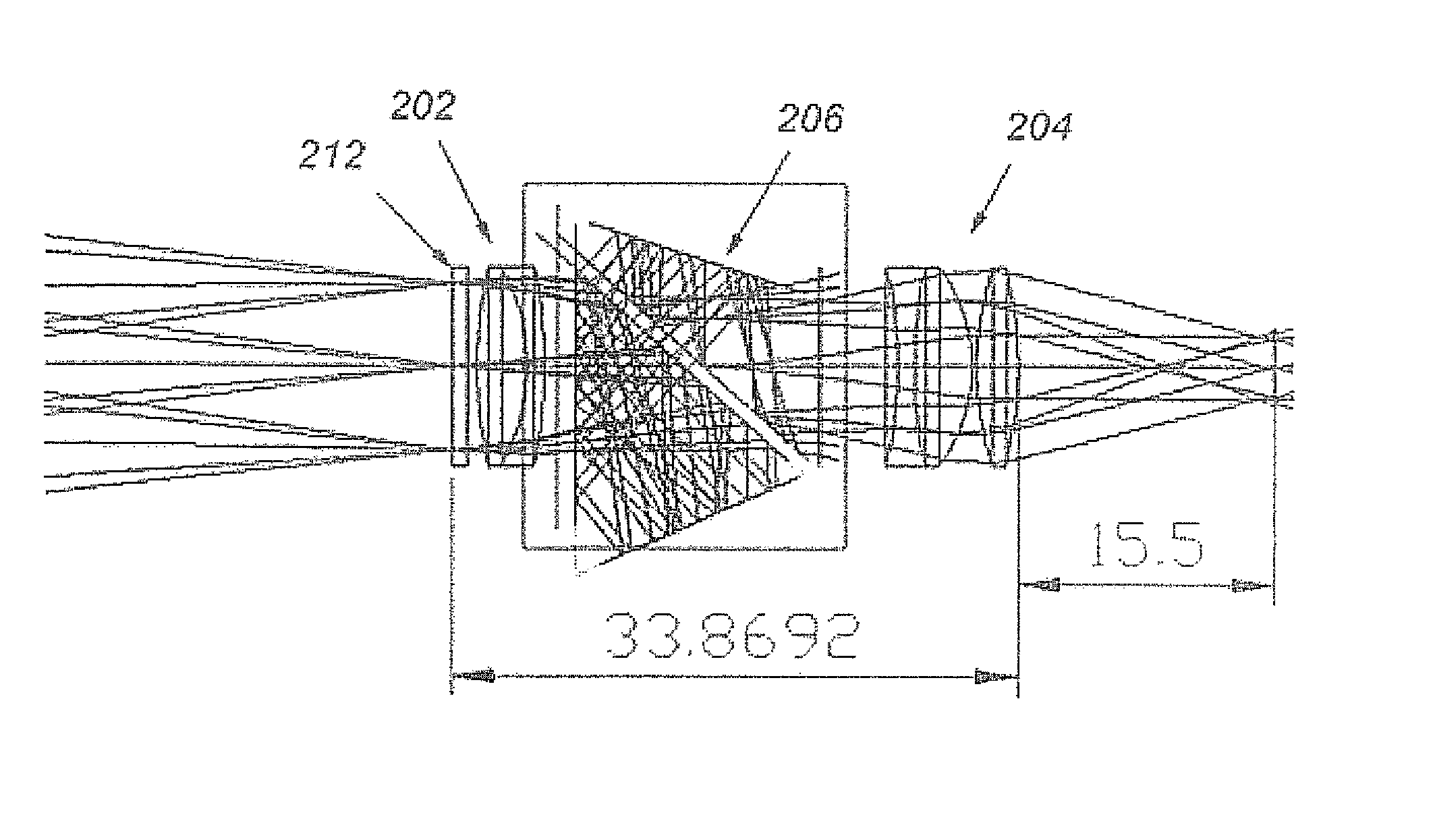
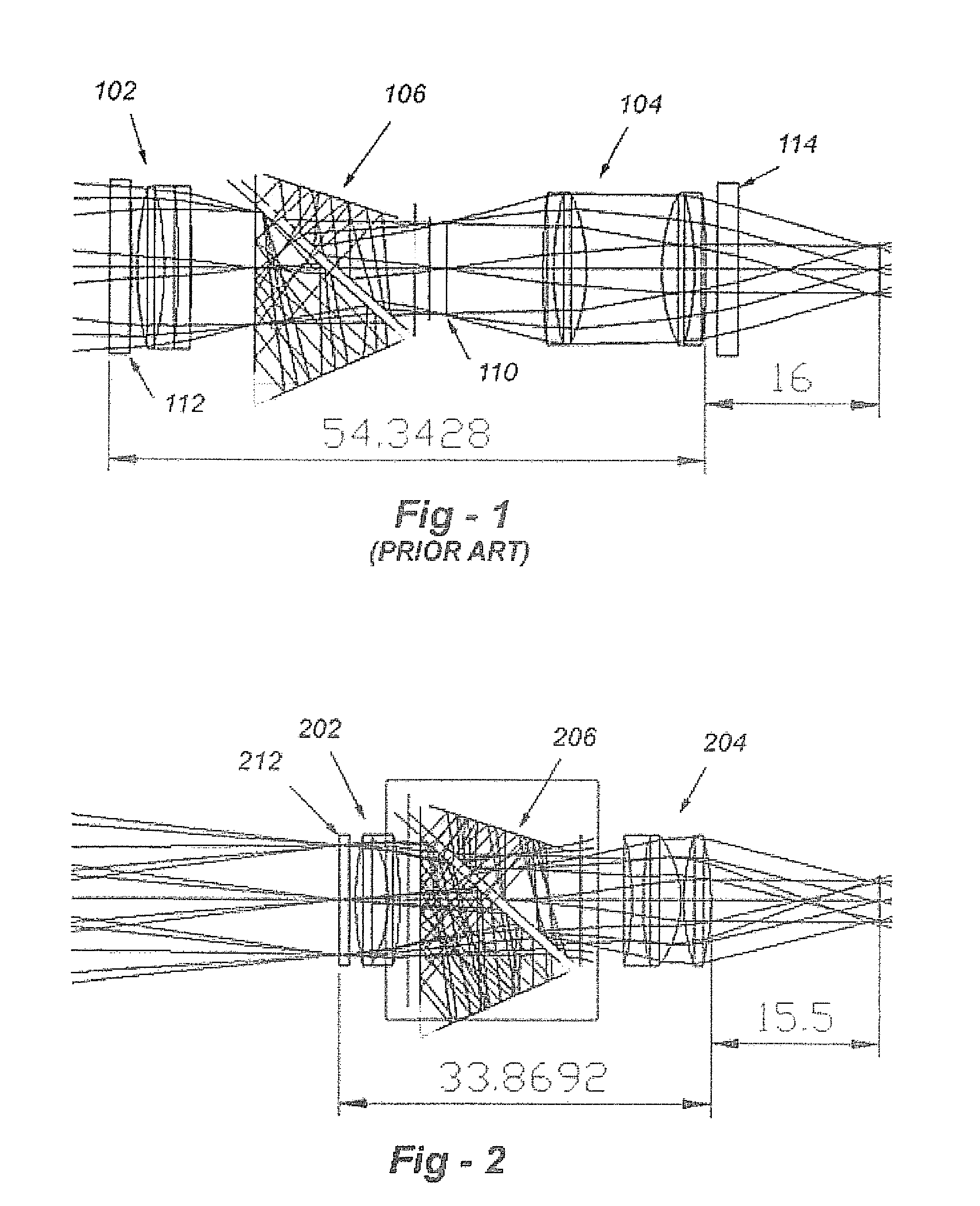
[0009]Having described the prior-art configuration of FIG. 1, reference is now made to FIG. 2, which shows a preferred embodiment of the invention. The objective lens elements 202 and 212, the eyepiece is shown at 204, and the image-rotating assembly (prisms) is shown at 206. In contrast to existing designs, the objective elements and eyepiece function to locate the image plane within the image-rotator itself, thereby enabling all of the components to be mounted in closer proximity for a much shorter design. Indeed, in the configuration shown in FIG. 2, for a working distance of 400 mm (15.7 inches), and magnification of 3.42×, the distance between the front and rear of the telescope is less than 34 mm, and even with the distance between the eyepiece and the eye 216 being 15.5 mm, the design is less than 50 mm in length overall.

[0010]This invention features other optical improvements, the certain of which are optional and may be used independently to improve other types of optical c...


PUM


Abstract

A compact Keplerian optical system includes a telescope having an image-rotator (Pechan roof prism pair), and an eyepiece and objective lens operative to form an intermediate image plane within the image-rotator, thereby decreasing the overall length. The objective lens optionally forms part of a replaceable cap, and plurality of replaceable caps may be provided, each with a different focal length to adjust for working distance. In the preferred embodiments, the eyepiece includes a singlet and a doublet lens to minimize eyestrain, and the objective lens includes a doublet and singlet field lens operative to increase depth of field and field of view. A practical implementation includes a pair of the telescopes, one for each eye of a user. Such a configuration may take the form of loupes mounted relative to eyeglass frames for surgical, medical or dental viewing applications.

Description

FIELD OF THE INVENTION[0001]This invention relates generally to magnifying optics and, in particular, to an improved Keplerian optical system having a shorter length and improved performance.BACKGROUND OF THE INVENTION[0002]To assist physicians, surgeons and dentists in observing smaller body parts, various telescopes or loupes are commercially available. These loupes are typically either of the Galilean or Keplerian design types, which may be pivotally mounted on eyeglass frames or fixed into the lens.[0003]Keplerian optics design is typically used for higher magnification applications, and image-rotating components such as a pair of roof Pechan prisms is typically utilized to form an erect image. Such prisms are relatively heavy, and are located in the optical path in between the objective and the eyepiece.[0004]A typical prior-art telescopic loupe based upon a Keplerian optical system is shown in FIG. 1. The objective lens shown generally at 102, the eyepiece lens is shown genera...

Claims


Application Information

Patent Timeline
Patent Type & Authority Patents(United States)
IPC IPC(8): G02B25/00G02B23/00
CPCG02B23/00G02B7/002
Inventor KIM, RICHARD C.WILLOUGHBY, CHARLES T.
Owner GEN SCI
Learn More