

Illumination source and method therefor
a technology of illumination source and illumination source, which is applied in the field of system and method of displaying images, can solve the problems of hammering the development of extremely small display system, and achieve the effects of reducing mechanical tolerance, reducing the cost of maintenance, and eliminating the need for illumination sour
- Summary
- Abstract
- Description
- Claims
- Application Information
AI Technical Summary
Benefits of technology
Problems solved by technology
Method used
Image

Examples
Embodiment Construction
[0024]The making and using of the embodiments are discussed in detail below. It should be appreciated, however, that the present invention provides many applicable inventive concepts that can be embodied in a wide variety of specific contexts. The specific embodiments discussed are merely illustrative of specific ways to make and use the invention, and do not limit the scope of the invention.
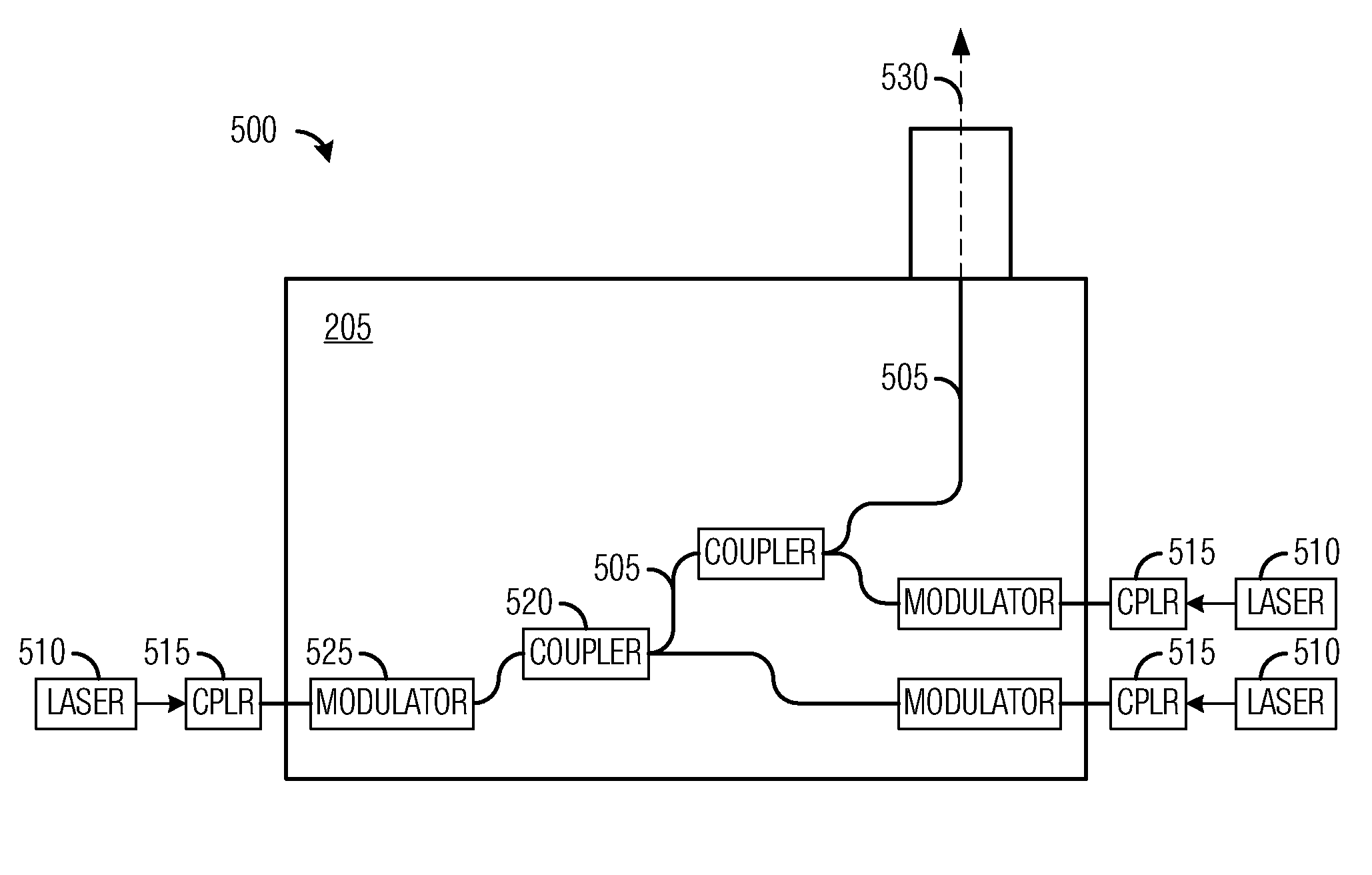
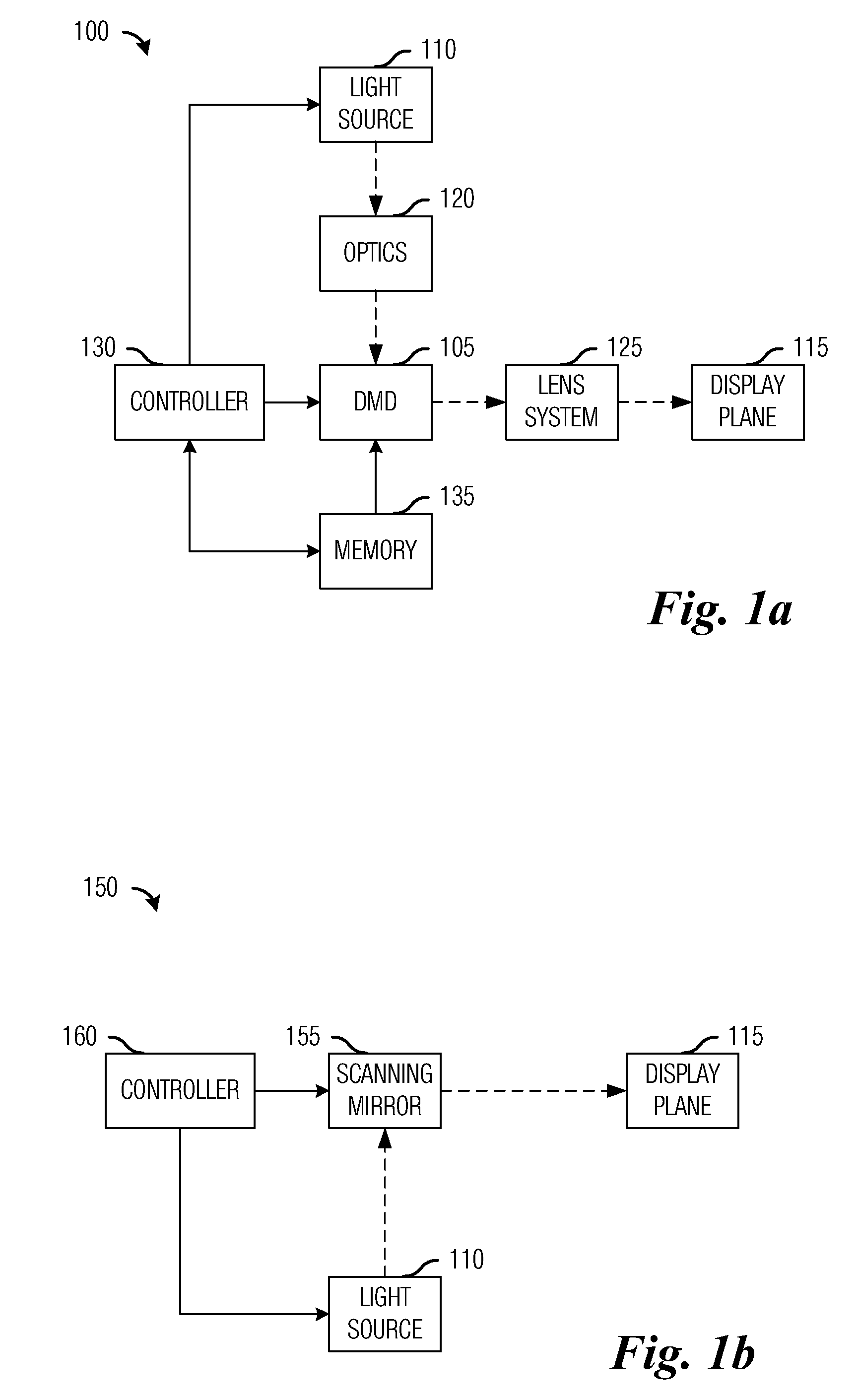
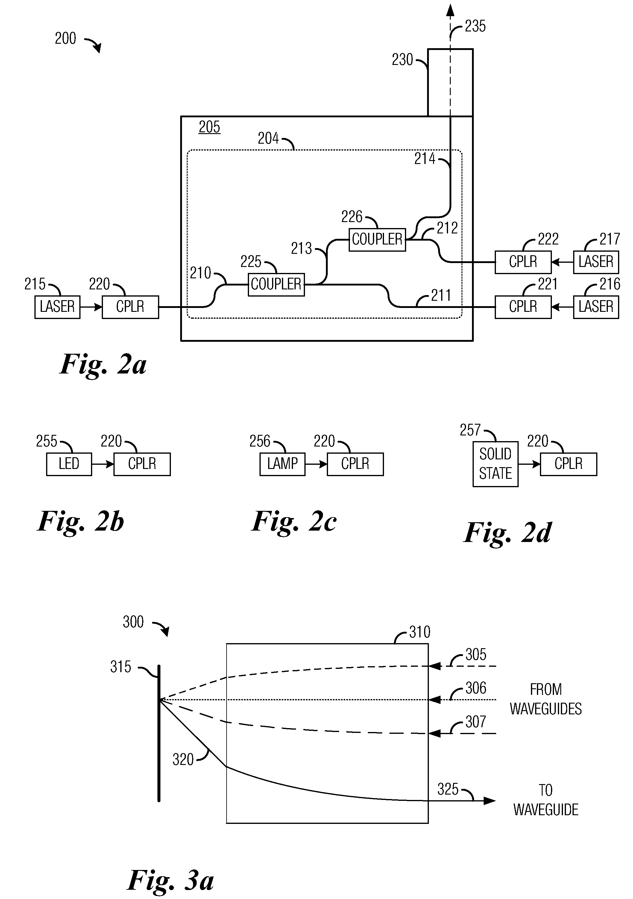
[0025]The embodiments will be described in a specific context, namely a laser illumination source for use in a DMD-based display system. The invention may also be applied, however, to illumination sources using other forms of illumination, such as electric arc lamp, light emitting diode and other solid-state light sources, as well as other forms of coherent light. The illumination source may be used in other forms of display systems, such as those utilizing transmissive or reflective liquid crystal displays, liquid crystal on silicon, ferroelectric liquid-crystal-on-silicon, deformable micromirr...
PUM
 Abstract
Description
Claims
Application Information