
Control device of mobile communication system

a control device and mobile communication technology, applied in the field of mobile communication, can solve the problems of increasing electric power consumption, wasting electric power, and affecting the efficiency of timing control, so as to reduce power consumption of mobile terminals, avoid unnecessary system switching, and make appropriate determination of system switching of mobile terminals quickly

Inactive Publication Date: 2010-05-18
NTT DOCOMO INC
View PDF35 Cites 1 Cited by
  • Summary
  • Abstract
  • Description
  • Claims
  • Application Information

AI Technical Summary

Benefits of technology

[0015]A more specific object of the present invention is to provide a control device able to switch communication of a mobile terminal communicating with one system to communication with the other system through appropriate control, while reducing power consumption and load of the mobile terminal.
[0020]According to the above invention, because the control device measures the position of the mobile terminal, the mobile terminal in communication with the first mobile communication system need not constantly monitor the control signal from the second mobile communication system, so power consumption of the mobile terminal can be reduced. In addition, by using the position data table that can be created in advance, appropriate determination for control of system switching of the mobile terminal can be made quickly. Compared with the method using the levels of the received signals, unnecessary system switching is avoidable. In addition, by taking into consideration changes of position of the mobile terminal, a detailed position data table can be created and system switching control can be performed appropriately in various situations.
[0021]Furthermore, because the first mobile communication system and the second mobile communication system have at least partially the same upper communication protocol layer, handover processing between two systems can be carried out smoothly. Different from the levels of the received control signals, position information does not depend on the types of the physical layers, so it is adequate to measure the position of the mobile terminal in the system in communication, and it is not necessary to measure the position of the mobile terminal for a physical layer of each of the two systems.

Problems solved by technology

As a result, consumption of electric power increases greatly.
In addition, the control signals have to be monitored constantly no matter whether the transmission mode of the mobile terminal needs to be switched or not, so, the electric power is wasted if system switching does not occur.
But generally, timing control places a heavy workload on a mobile terminal.
Accordingly, for a mobile terminal having to pay attention to power consumption, this method is not appropriate.
Therefore, sometimes system switching is actually not necessary or this switching is not actually possible even though the levels of the received signals are higher than the preset value.
In this case, if such kind of switching is still carried out, this also leads to unnecessary power consumption.

Method used


Image

  • Control device of mobile communication system
  • Control device of mobile communication system
  • Control device of mobile communication system

Examples


first embodiment

The First Embodiment

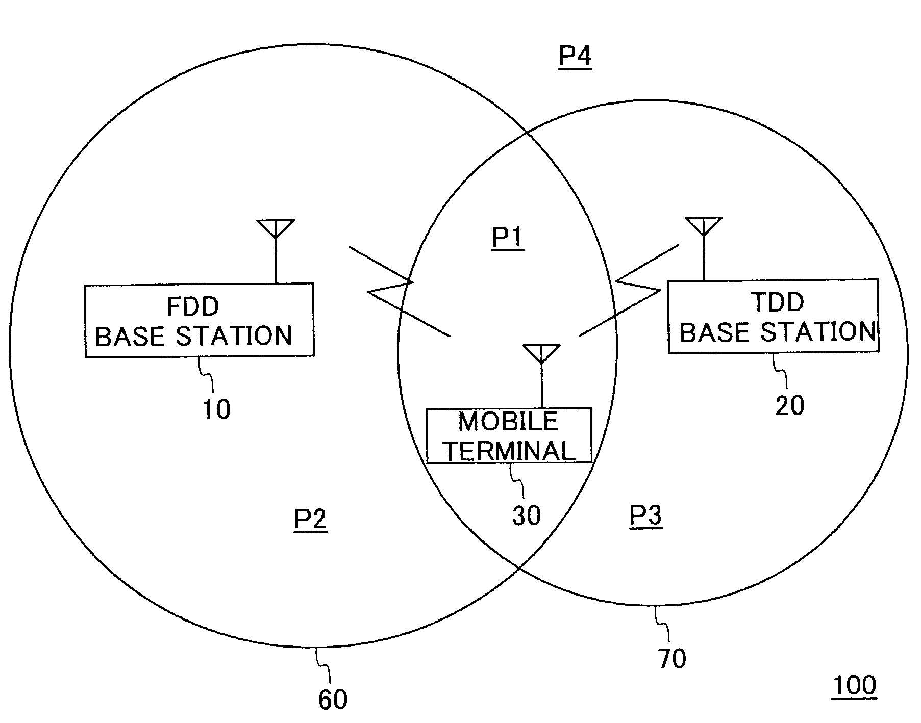
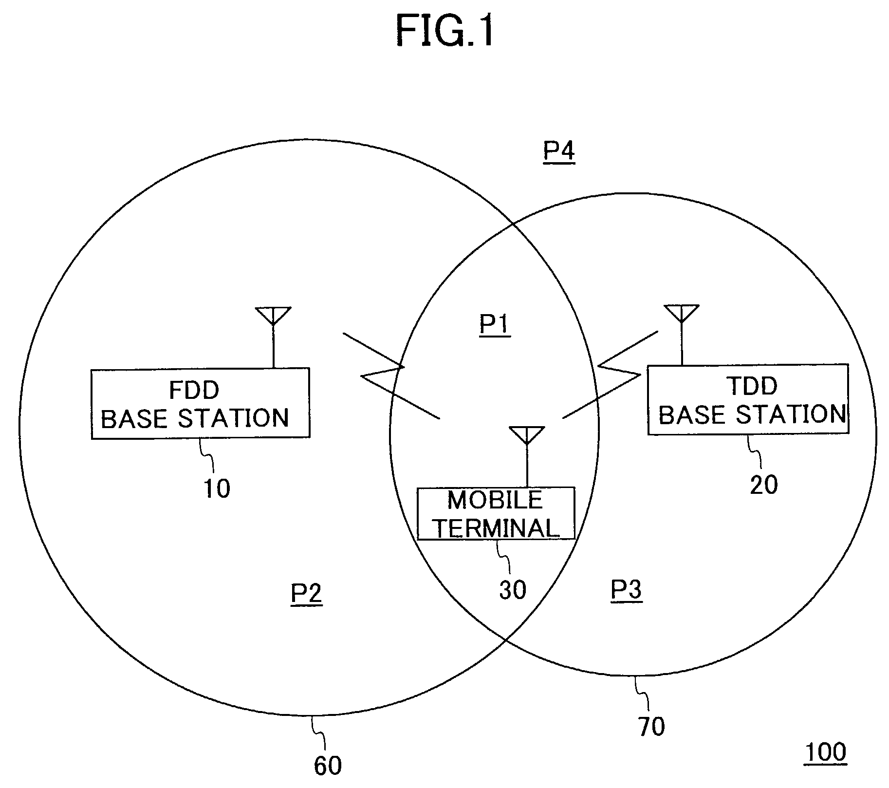
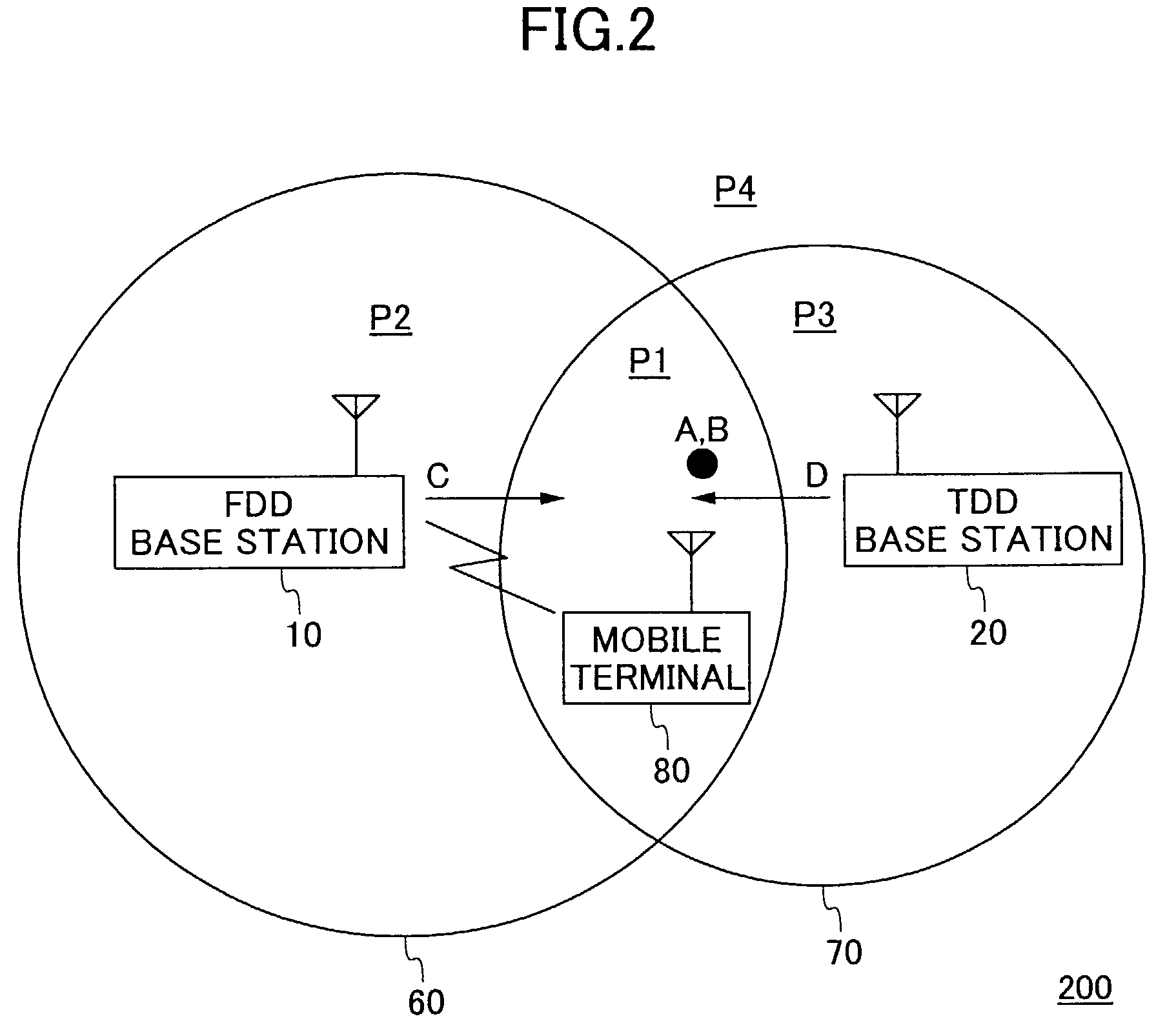
[0031]FIG. 2 is a schematic view showing a mobile communication system 200 according to a first embodiment of the present invention. The basic configuration of the mobile communication system 200 shown in FIG. 2 is the same as that of the mobile communication system 100 shown in FIG. 1. That is, the mobile communication system 200 includes an FDD base station 10 constituting an IMT-2000 / FDD system, a TDD base station 20 constituting an IMT-2000 / TDD system, and a mobile terminal 80 operable in either of the above two systems. Similarly, the FDD base station 10 provides services in a service area 60 and the TDD base station 20 provides services in a service area 70. The FDD service area 60 and the TDD service area 70 are partially overlapped geographically. Further, in FIG. 2, P1, P2, P3 indicate the overlapped common area of the service area 60 and the service area 70, the area in the service area 60 other than the overlapped area P1, and the area in the service a...

second embodiment

The Second Embodiment

[0063]FIG. 6 is a schematic view showing a mobile communication system 600 according to a second embodiment of the present invention. The basic configuration of the mobile communication system 600 is the same as that of the mobile communication system 200 shown in FIG. 2, except that the overlapped area of the FDD service area 60 and the TDD service area 70 are divided into the area P1 and the area P5.

[0064]FIG. 7 is an example of the position data table 45 in the control unit 40 in the mobile communication system 600.

[0065]The same as the table 500 shown in FIG. 5, in the table 700 shown in FIG. 7, the letters A through J in the leftmost column are line indices, the second column from the left contains the previous positions of the mobile terminal 80, the third column from the left shows the present positions of the mobile terminal 80, the fourth column shows the present transmission method, and the rightmost column exhibits the contents of instructions. The po...


PUM


Abstract

There is provided a control device enabling switching of communication of a mobile terminal with one system to communication with another system while reducing power consumption and workload of the mobile terminal. The control device is used in a communication system including a first mobile communication system, a second mobile communication system, and a mobile terminal being in communication with the first mobile communication system. The control device comprises a position measuring unit for measuring the position of the mobile terminal, a judgment unit for making a determination whether or not to switch the communication of the mobile terminal from the first mobile communication system to the second mobile communication system according to a position measurement result of the position measuring unit, and a switching unit for performing the above switching operation according to the determination of the judgment unit.

Description

BACKGROUND OF THE INVENTION[0001]1. Field of the Invention[0002]The present invention relates generally to the field of mobile communications, and more specifically to a control device enabling handover between mobile communication systems.[0003]2. Description of the Related Art[0004]The so-called IMT-2000 (International Mobile Telecommunications 2000) system is well known in the field of mobile communications, and is capable of meeting requirements of high-speed communications, for example, at 2 Mbps. There are two standardized transmission methods in IMT-2000 systems, one is IMT-2000 / FDD (Frequency Division Duplex), and the other is IMT-2000 / TDD (Time Division Duplex). FDD is capable of providing wide area services with symmetric traffic for downlink and uplink channels, and therefore is suited to data and speech transmission with lower data rate, such as 384 kbps. On the other hand, TDD is capable of dynamically varying the traffic of downlink and uplink channels, and is preferre...

Claims


Application Information

Patent Timeline
IPC IPC(8): H04W36/00H04L45/80H04W36/14H04W36/38H04W40/34H04W64/00H04W76/02
CPCH04W36/32H04W36/14Y02B60/50Y02D30/70H04W36/322
Inventor ISHIGURO, TAKAYUKIYAMADA, MAYUMOON, SUNG UKISHII, HIROYUKIFUTAKATA, TOSHIYUKIDOHI, TOMOHIRO
Owner NTT DOCOMO INC
Learn More